PSOC™ 6 Artificial Intelligence Evaluation Kit
The PSOC™ 6 AI Evaluation Kit is a hardware platform focused on Machine Learning (ML), that allows you to evaluate DEEPCRAFT™ Studio, DEEPCRAFT™ Studio Accelerators and other software products. The kit is engineered for seamless prototyping and includes a range of sensors, such as 6-axis motion sensor, magnetometer, barometric pressure sensor, and radar sensor for data collection and developing machine learning models.This kit features a PSOC™ 6 MCU, a CYW43439 Wi-Fi/Bluetooth® combo module, a 512-Mb NOR flash, an onboard programmer/debugger (KitProg3), PDM-PCM digital microphone interface, full-speed USB device, two user LEDs, and one user button. The board supports operating voltages from 1.8 V to 3.3 V for the PSOC™ 6 MCU. For more information, refer to CY8CKIT-062S2-AI .
Kit contents
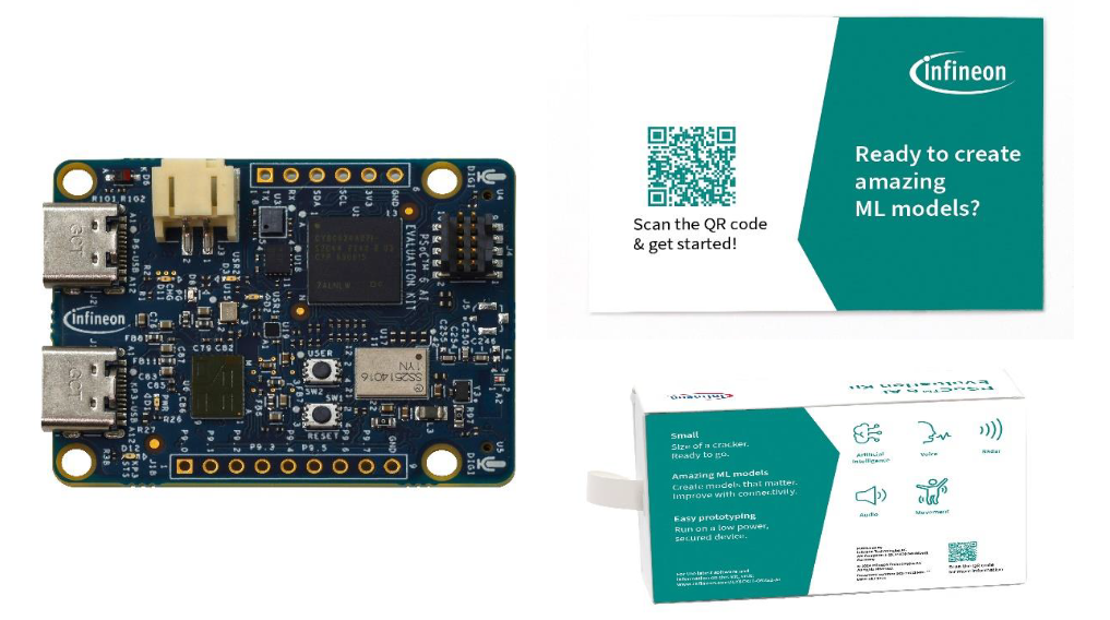
The kit includes the following:
- PSOC™ 6 AI Evaluation Board (CY8CKIT-062S2-AI)
- Inlay card (a printed QR code points to a getting started webpage)
 |
|---|
Streaming Firmware for PSOC™ 6 AI Evaluation Kit
PSOC™ 6 AI Evaluation Kit comes pre-programmed with streaming firmware that can stream sensor data from the USB port into DEEPCRAFT™ Studio for machine learning model creation. The streaming firmware is designed to collect data from all the sensors Integrated into the kit, including the microphone, accelerometer, gyroscope, magnetometer, pressure sensor, radar.
PSOC™ 6 AI Evaluation kits manufactured before March, 2025 are utilizing the old streaming firmware (implemented using protocol version 1), see the assembled date printed in the format (YYWW), on the label located on the side of your kit box. We have developed a new streaming firmware that uses Tensor Streaming Protocol Version 2, offering improved functionality. We recommend flashing the kits with the new streaming firmware to take advantage of these enhancements. Note that the PSOC™ 6 AI Evaluation kits manufactured after February, 2025 will come pre-programmed with the new streaming firmware. Refer Tensor Streaming Protocol for Real-Time Data Collection to know more about the protocols.
Flashing the Streaming Firmware
To flash the streaming firmware onto the kit, follow the pre-requisites and steps outlined below:
Pre-requisites:
- Streaming Firmware - PSOC™ 6 AI Evaluation Kit (HEX File - hosted on 2026‑01‑08)
- Download and Install ModusToolbox™ Programmer (Flash Utility)
- PSOC™ 6 AI Evaluation Kit (CY8CKIT-062S2-AI)
- Register an account and Install DEEPCRAFT™ Studio
We now offer streaming data over Wi‑Fi for PSOC™ 6 AI Evaluation Kit. If you want to enable the Wi‑Fi data streaming functionality, re-flash the kit with the hex file hosted on 2026‑01‑08. The hex file includes firmware for both Wi‑Fi and serial data streaming. If you flashed the board before 2026‑01‑08, you can only stream data over serial connection. After flashing the kit with the hex file, you need to enable Wi‑Fi on the board to start streaming. For step‑by‑step instructions, see How to stream data into Studio over Wi-Fi network.
Steps to flash the Streaming Firmware onto the PSOC™ 6 AI Evaluation Kit
-
Download and unzip the hex file to flash the Streaming Firmware onto the board.
-
Connect the KitProg3 USB connector (J1) port on the board to the PC using the USB cable.
-
Open ModusToolbox™ Programmer from the Windows Start menu. The ModusToolbox™ Programmer window appears.

-
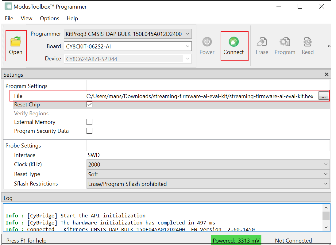
In Programmer drop-down box, select the device type as KitProg3 CMSIS-DAP BULK-XXXXXXXXXXXXXXXX.
-
In Board drop-down box, select the board type as CY8CKIT-062S2-AI.
-
Click Open and navigate to select the Streaming Firmware (hex file) downloaded earlier.
-
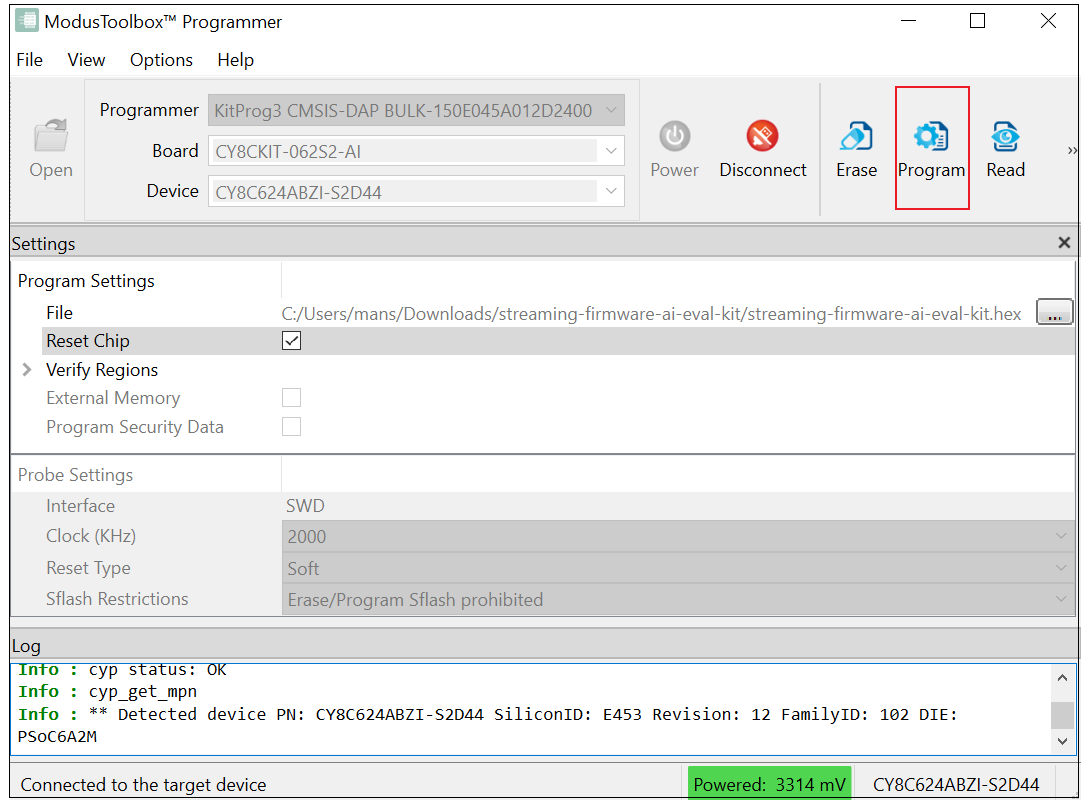
Click Connect to establish a connection between the board and the ModusToolbox™ Programmer.
-
Click Program to flash the Streaming Firmware on the board. The kit is programmed successfully.
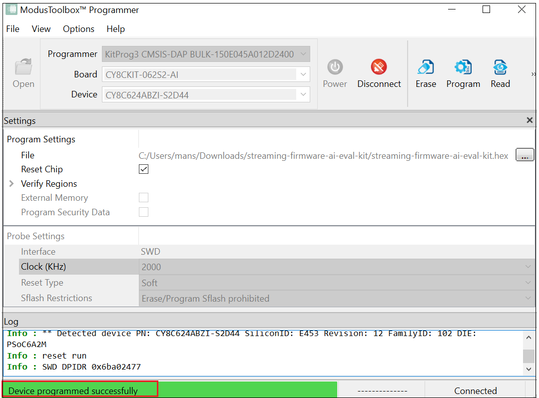
Now, disconnect the KitProg3 USB connector (J1) port and connect the KitProg3 USB connector (J2) port with the PC using the USB cable. After you have flashed the new firmware, follow Real-Time Data Collection with PSOC™ 6 AI Evaluation Kit using the new streaming firmware to stream data from the PSOC™ 6 AI Evaluation Kit. If you have not yet flashed the new streaming firmware follow Real-Time Data Collection with PSOC™ 6 AI Evaluation Kit using the old streaming firmware section to stream data into Studio.