Code Generation for Infineon PSOC™ 6 and PSOC™ Edge boards
For generating code for computer vision models, refer to Code Generation for Vision Models.
This section provides step-by-step information on generating, optimizing and validating the code for Infineon PSOC™ 6 and PSOC™ Edge boards. After training and evaluating a model, the next step is code generation. You have the option to generate the code for the model with or without optimization.
Understanding Model Optimization
Model optimization involves refining the code to enhance performance, efficiency, and accuracy on the development boards. This process ensures that the model runs smoothly and effectively in various environments. By optimizing the model, you can reduce computational costs, improve execution speed, and achieve better overall results. You can optimize the preprocessor as well as the network to enhance the model efficiency and performance. Studio provides several options to optimize the preprocessor using the CMSIS-DSP Library. The CMSIS (Cortex Microcontroller Software Interface Standard) library provides a robust framework for this optimization. By leveraging the CMSIS library, you can enhance the computational efficiency and overall effectiveness of your model, ensuring the model runs seamlessly and meets performance expectations.
Understanding Model Validation
Model validation involves validating the performance of the optimized model by checking the performance against test data (accuracy), and visualize the implementation resource requirements, such as the number of cycles to run the inference engine and the memory size of the neural network model and inference working memory. The report includes data on the inference engine when running on a computer (reference model with the best accuracy and higher memory requirements), and on the target device (limited hardware resources).
ModusToolbox™ Integration
To bridge DEEPCRAFT™ Studio and ModusToolbox™, we provide a bidirectional integration that supports an end‑to‑end workflow for PSOC™ Edge boards. A Studio project is needed to train the model and a ModusToolbox™ project is needed to deploy the model. The integration offers the following capabilities:
-
Bidirectional access: Launch Studio from ModusToolbox™ and launch ModusToolbox™ Project Creator from Studio. When you create a ModusToolbox™ project from Studio using the Project Creator or launch DEEPCRAFT™ Studio from ModusToolbox™ project via Quick Panel, in both scenarios, the project paths are automatically saved in Studio.
-
Automatic code transfer: During code generation, the saved ModusToolbox™ project paths are available as selectable output locations in DEEPCRAFT™ Studio. Select the required ModusToolbox™ project to generate the code directly into the project, making convenient to deploy the model onto the PSOC Edge board.
-
Open Studio project from ModusToolbox™: After you generate code in a ModusToolbox™ project, a Design.deepcraft file is created along with the model files. Double-click the Design.deepcraft file (or use the Quick Panel) to launch Studio with the project which was used to train the model set as the workspace.
-
The
.Design.deepcraftfile is overwritten if you generate code to the same output directory. -
Having multiple
Design.deepcraftfiles in the same project is not supported. -
To generate the
.design.deepcraftfile, the following requirements must be met:- The training for the model you want to generate code for, is started after the release of this functionality (2025-09-12)
- The model is present in the directory of the Studio project used for training.
- The Studio project used for training is present in the current workspace of DEEPCRAFT Studio.
Depending on whether you have a ModusToolbox™ project, a Studio project, both, or neither, use the following workflows to link DEEPCRAFT™ Studio and ModusToolbox™:
-
You have no Studio project and no ModusToolbox™ project: Create both the projects from DEEPCRAFT™ Studio. Depending on the project you want to create, refer to How do I use a Project Template? or How do I get started with Studio Accelerators?.
-
You have an existing DEEPCRAFT™ Studio project but no ModusToolbox™ project: Create the ModusToolbox™ project with ModusToolbox™ Project Creator (either the standalone app or from the ModusToolbox™ IDE). Now, launch DEEPCRAFT™ Studio from ModusToolbox™ to auto-save the project path in Studio.
-
You have an existing ModusToolbox™ project but no Studio project: The easiest way to create a project in studio is to launch Studio from ModusToolbox™, which automatically saves the ModusToolbox™ project path in Studio. In ModusToolbox™ Eclipse IDE, launch Studio via use Quick Panel > Library Configurators > DEEPCRAFT™ Studio. In VS Code with ModusToolbox™ Assistant plugin, launch studio via Quick Links > DEEPCRAFT™ Studio (ensure a project is selected in the Explorer for the link to appear). After Studio launches, depending on the type of project you want to create, refer to How do I use a Project Template? or How do I get started with Studio Accelerators?. Alternatively, create the project in Studio directly and select the ModusToolbox™ project path during code generation.
-
You have an existing ModusToolbox™ project and Studio project: Link the projects during code generation in Studio. To do so, click the three horizontal dots in the project path and select the ModusToolbox™ project. Refer to ModusToolbox™ Project to know more.
How to generate the Code?
To generate the code, follow the steps:
-
Navigate to your project directory and open the the model file (*.h5).
-
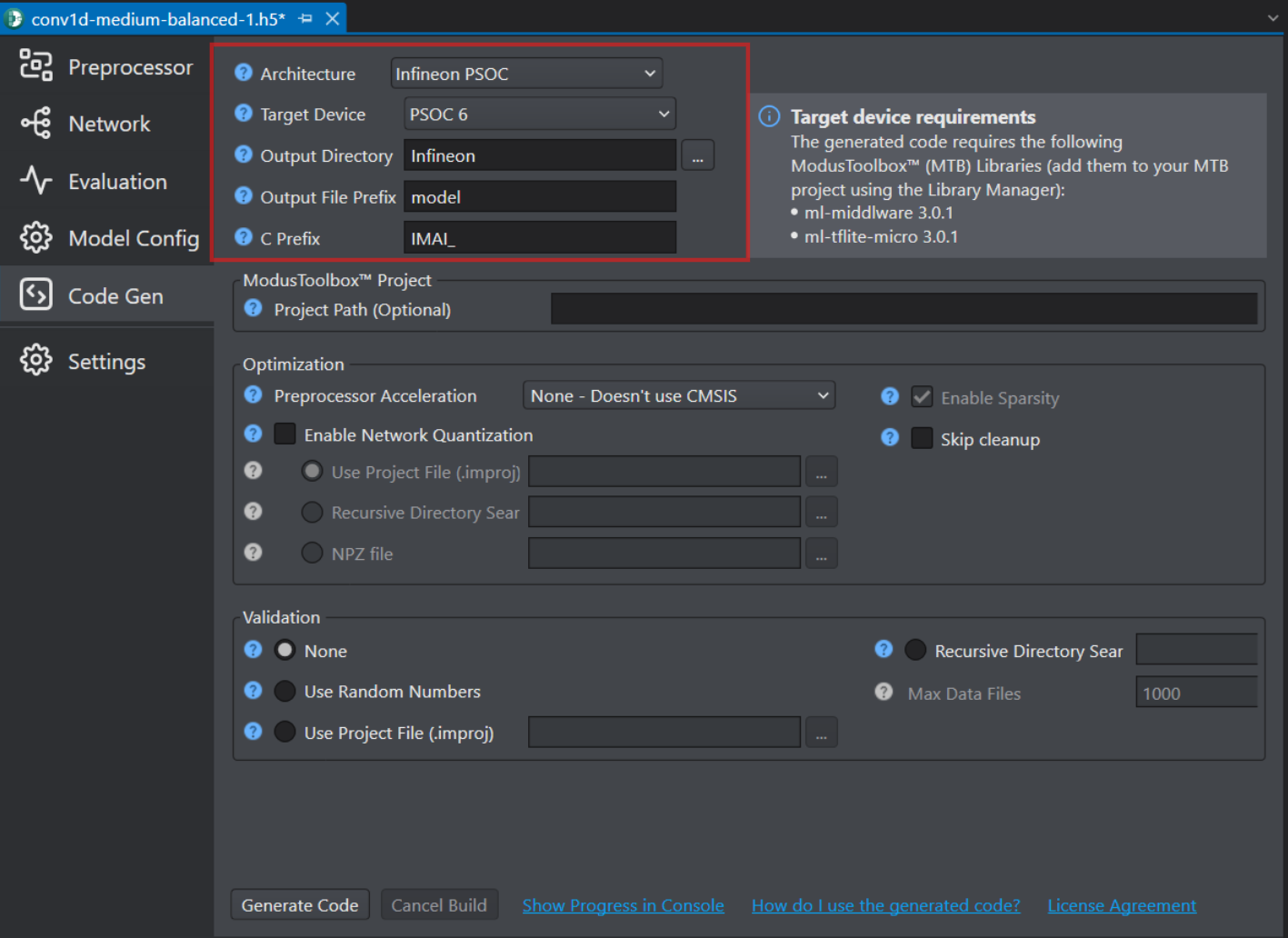
Click the Code Gen tab on the left pane and configure the following parameters:
-
In Architecture, select Infineon PSOC as the architecture type.
-
In Target Device, select the required Infineon board or core type from the following options - PSOC 6, PSOC Edge M33/NNLite, PSOC Edge M55/U5, PSOC Edge M55.
-
Before generating code for PSOC targets, ensure that your model only uses the layers and operators listed as supported in the Supported layers and operators for PSOC Targets table. If your model contains any layers or operators that are not supported, select the ANSI C99 architecture type. For instructions on generating code using the ANSI C99 architecture, refer to Code Generation for Infineon AURIX, Traveo, XMC7200 and Other Development Boards.
-
In Output Directory, browse and select the directory where you want to save the generated code. By, default Infineon is selected as the default folder.
-
In Output File Prefix, enter the prefix to be added at the beginning of the generated file names.
-
In C Prefix, enter the prefix to be added to generated API functions so as to avoid naming collisions with functions created outside Studio.
ModusToolbox™ Project
In Project Path, select the path to the root directory of the ModusToolbox™ project, where you want to save the generated code. For multicore applications, select the root directory of the single‑core project. The generated code is saved in the folder specified in the Output Directory defined above, relative to the selected ModusToolbox™ project path. For example, if the ModusToolbox™ project path is “C:\Some\Path\Workspace\Project” and Output directory is models, the output is saved to “C:\Some\Path\Workspace\Project\models”.
The ModusToolbox™ project path appears in the dropdown in the following scenarios:
- You launched Studio from the ModusToolbox™ projects via the Quick Panel in ModusToolbox™.
- You create the ModusToolbox™ project by launching the Project Creator from the DEEPCRAFT Studio New Project Wizard. To know more, refer to
- You previously selected the project for code generation using this functionality.
If an existing ModusToolbox™ project does not appear in the dropdown, click the three dots to browse and select the project path. The selected project path will appear the next time you generate code.
To remove a saved ModusToolbox™ project path, click the X icon next to the path.
After setting the parameters, you have two options: optimize the model or proceed without optimization, depending on your requirements. If you select not to optimize, you can skip directly to step 7 and follow the subsequent steps to generate the code. However, if you prefer to optimize the model, follow the steps to set the optimization parameters before generating the code.
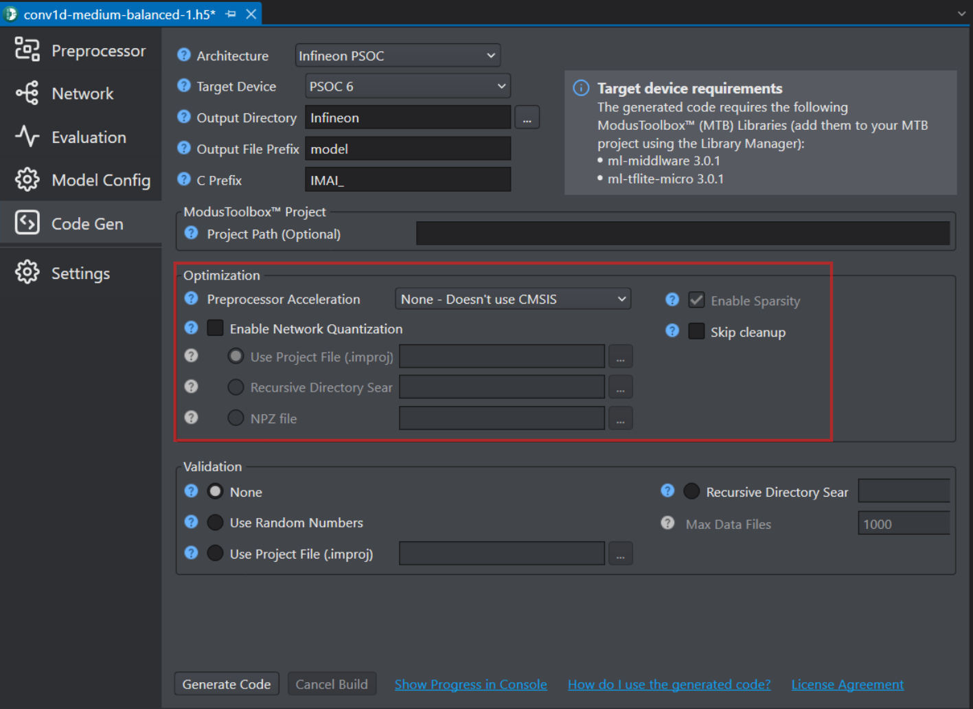
Optimization
-
In Preprocessor Acceleration, optimize the code using the CMSIS-DSP Library by selecting the one of the following options:
-
None-Don’t use CMSIS, if CMSIS is not supported on the target board.
-
CMSIS Floating Point (Float32), provides accelerated float 32 arithmetic, making this option an excellent choice for target boards with an ARM Core featuring a Floating Point Unit (FPU). This option is compatible with all units, including non-accelerated custom units. This option is user-friendly, offers good performance, but necessitates the presence of an FPU.
-
CMSIS Shifted Fixed Point 16 Bit (Q15), for excellent performance on target boards without an FPU, achieving similar efficiency to CMSIS Float32 on boards with an FPU. This option uses only 16 bits, consuming half the memory compared to CMSIS Float32. However, implementing support for this type in all custom units can be complex.
-
CMSIS Shifted Fixed Point 16 Bit (Q31), if you require high-resolution (32-bit) on your features and your target board lacks an FPU.
-
-
Check the Enable Network Quantization checkbox, if you want to quantize the network code along with the preprocessor code. If you enable this option, you must provide calibration data to generate a 8-bit quantized model.
- In Use Project file (.improj), select the radio button to provide the calibration data using the project file. When this option is enabled, the calibration data will be utilized from the training set.
OR - In Recursive Directory Search, select the radio button to provide the calibration data from the desired directory.
- In Use Project file (.improj), select the radio button to provide the calibration data using the project file. When this option is enabled, the calibration data will be utilized from the training set.
-
Select the Enable Sparsity checkbox to further optimize the model by packing sparse weights, thereby saving memory when deploying the model on the target device.
-
Select the Skip Cleanup checkbox to not delete the certain temporary files created during code generation. If necessary, you can delete these files manually at a later time. When this checkbox is disabled, the temporary files are deleted automatically.
Advanced optimization for PSOC™ Edge M55+U55
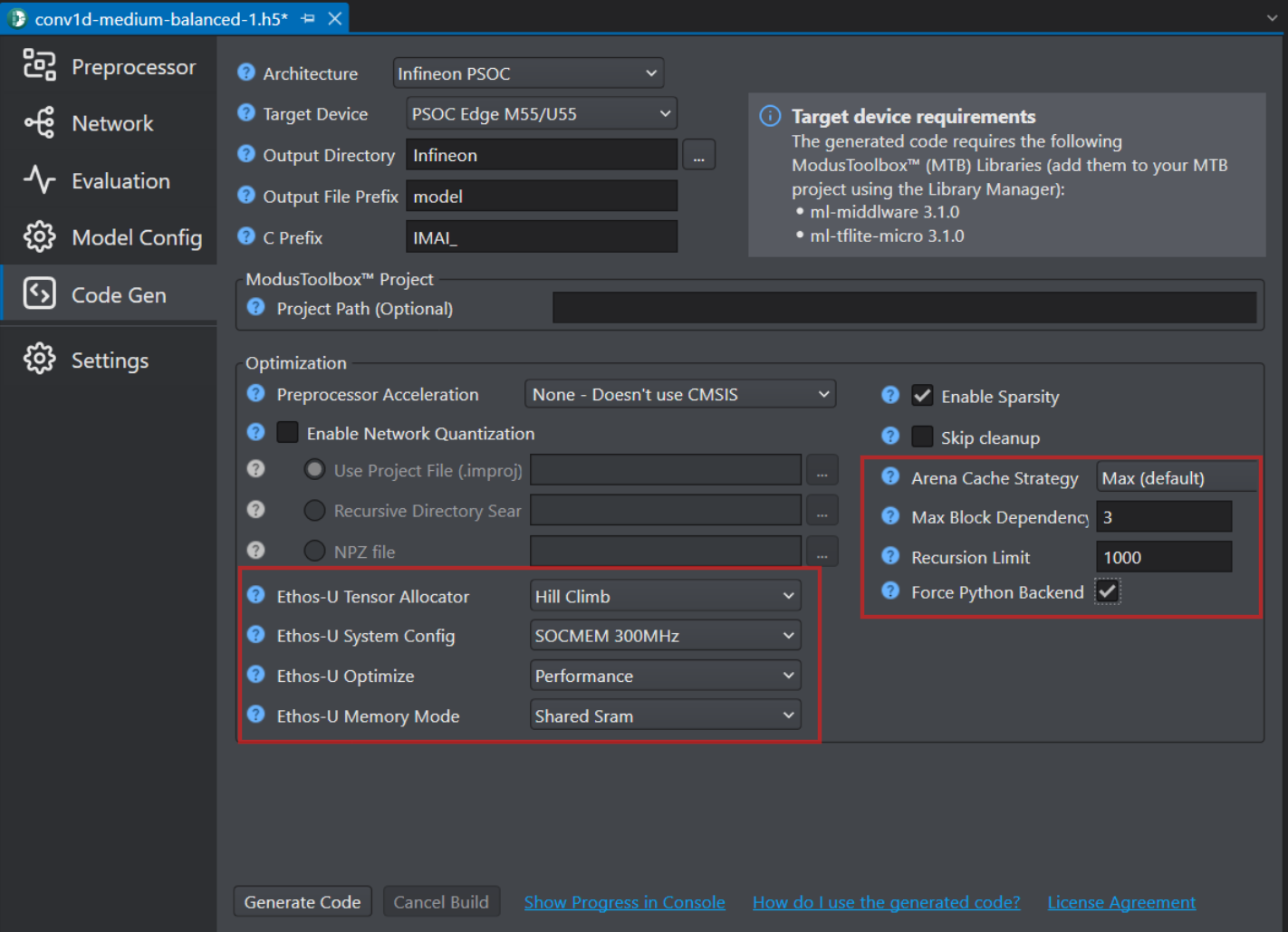
The following optimization settings are part of the Vela compiler and generate optimizations for code targeting the Ethos-U55 NPU. These options reduce scratch memory usage with minimal to no impact on model accuracy.
| Parameters | Description |
|---|---|
| Ethos-U Tensor Allocator | Select Linear Alloc, Greedy or Hill Climb to specify the algorithm for allocating non‑constant tensors on the NPU and CPU. By default, Hill Climb is selected. |
| Ethos-U System Config | Select SOCMEM 300MHz or SOCMEM 200MHz as the system configuration of the Ethos-U NPU. Refer to Silicon documentation to know more. |
| Ethos-U Optimize | Select the optimization strategy based on Size or Performance. The Size strategy ensures minimal RAM usage by avoiding the use of the arena cache memory area size whereas the Performance strategy prioritizes maximal performance by utilizing the specified arena cache memory area size. By default, Performance strategy is selected. |
| Ethos-U Memory Mode | Select Shared SRAM or SRAM Only as the memory mode. Shared SRAM is shared between Ethos-U and Cortex-M software, whereas SRAM Only is dedicated to Ethos-U. The non-SRAM memory is read-only. By default, Shared SRAM is selected. |
| Arena Cache Strategy | Select the strategy to determine the arena cache size for Ethos-U55 NPU memory optimization: Min , Max or Custom. - When you select Min, the arena cache size is set to the minimum size required by the model. - When you select Max, the arena cache size is set to the maximum size allowed by the target platform. This is the default strategy. - When you select Custom, the arena cache size is set to the specified size manually. When this option is selected, the Arena Cache Size parameter becomes available. |
| Arena Cache Size | Set the size of the arena cache memory area, in bytes. The size of the arena cache memory area must be any integer greater than or equal to 0. By default, the value of arena cache memory is set as 2936012. The arena cache is an optimization hint for U55 acceleration. It is not the same as the overall tensor arena used by the model. This parameter is available only when the Arena Cache Strategy is set to Custom. |
| Force Python Backend | Enable this option to force the use of the deprecated Vela Python API backend for model optimization. When selected, additional advanced parameters related to the Python backend optimization flow are available, such as Max Block Dependencies and Recursion Limit. |
| Recursion Limit | Set the Python internal limit to depth of recursion. For very large networks, increasing the recursive limit may be necessary due to the recursive graph traversal algorithm. If generation fails with a RecursionError, increase the limit using this option. By default, the recursion limit is set as 1000. This option is applied only when the Force Python Backend option is enabled. |
| Max Block Dependency | Set the maximum value that can be used for the block dependency delay between NPU kernel operations. A lower value may result in longer execution time. You may set: 0, 1, 2 or 3 as the value for Npu block dependency. By default, the value of block dependency is set as 3. This option is applied only when the Force Python Backend option is enabled. |
After setting the parameters, you have two options: validate the model or proceed without validating the model, depending on your requirements. If you select not to validate, then select None under Validation and skip directly to step 9 and follow the subsequent steps to generate the code. However, if you prefer to validate the model, follow the steps to set the validation parameters before generating the code.
Validation
- It is highly recommended to specify the validation data, when validating the model. Testing the model with random data does not provide a reliable assessment of the quantization loss.
- Model validation option is not available for PSOC Edge M55/U55 target. However, support for model validation on PSOC Edge M55/U55 targets will be provided in the future.
- You can validate the model using any of the following options:
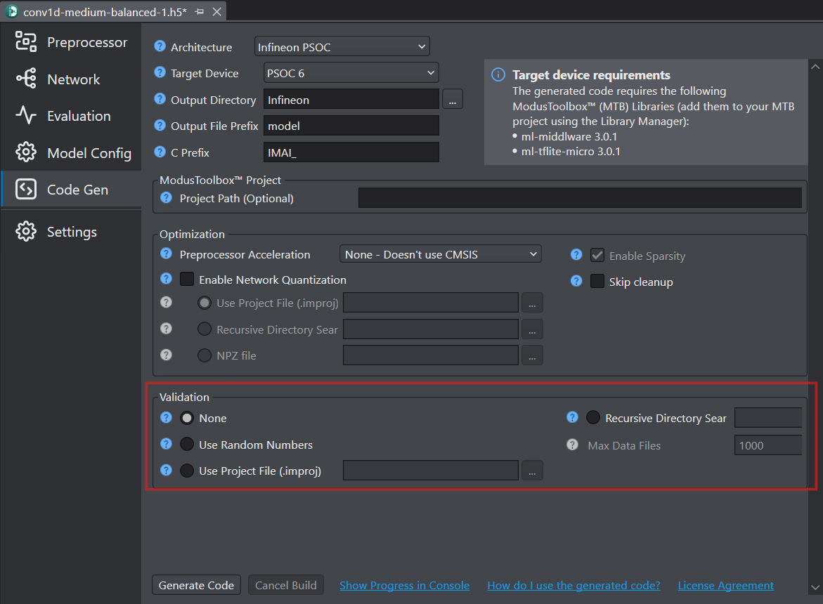
- Select Use Random Numbers, if you want to validate the model with random data
- In Use Project file (.improj), select the radio button to provide the validation data using the project file. When this option is enabled, the validation data will be utilized from the test set.
- In Recursive Directory Search, select the radio button to provide the validation data from the desired directory. Validate using .data and .wav files found recursively in the selected directory.
- In Max Data Files, enter the maximum number of files to use for validating the model. If the number of files in the selected directory exceeds the number entered in this parameter, a random subset of files will be selected for validation. If the validation fails due to out of memory errors, reduce the number of files.
-
Click Update Dependencies button to install the core tools to generate the code. This is one time installation and may take some time.
-
Once the core tools are installed, click the Generate Code button. The code (model.c and model.h files) is generated in the Output Directory defined earlier and a Model performance and validation report opens.
However, if you select the ModusToolbox™ project in the Project Path for code generation, Studio generates the model.c and model.h files in the ModusToolbox™ project, along with the design.deepcraft file.
After generating the code, lets deploy the code on the Infineon PSOC boards using ModusToolbox. To know how refer to Deploy model on PSOC™ 6 and PSOC™ Edge boards.
Supported layers and operators for PSOC Targets
Our code generation includes optimized operators for the PSOC microcontroller family. When you select the architecture type as PSOC during code generation, these optimized operators are used to maximize the runtime performance. If your model uses any layers or operators that are not listed as supported (checked) in the tables below, select the C99 architecture type.
| Network Layers/Operators | Architecture Type | |
|---|---|---|
| PSOC Target | Any Target (ANSI C99) | |
| Activation | ✓ | ✓ |
| Add | ✓ | ✓ |
| AveragePooling1D | ✓ | ✓ |
| AveragePooling2D | ✓ | ✓ |
| BatchNormalization | ✓ | ✓ |
| Concatenate | ✓ | ✓ |
| Conv1D | ✓ | ✓ |
| Conv2D | ✓ | ✓ |
| Dense | ✓ | ✓ |
| Dropout | ✓ | ✓ |
| Flatten | ✓ | ✓ |
| GlobalAveragePooling1D | ✓ | ✓ |
| GlobalAveragePooling2D | ✓ | ✓ |
| GlobalMaxPooling1D | ✓ | ✓ |
| GlobalMaxPooling2D | ✓ | ✓ |
| InputLayer | ✓ | ✓ |
| LeakyRELU | ✓ | ✓ |
| LSTM | ✓ | ✓ |
| MaxPooling1D | ✓ | ✓ |
| MaxPooling2D | ✓ | ✓ |
| RELU | ✓ | ✓ |
| Reshape | ✓ | ✓ |
| Softmax | ✓ | ✓ |
| Abs | ✓ | ✓ |
| Add_N | ✓ | ✓ |
| Arg_Max | ✓ | ✓ |
| Arg_Min | ✓ | ✓ |
| Dequantize | ✓ | ✓ |
| Fully_connected | ✓ | ✓ |
| Log | ✓ | ✓ |
| Maximum | ✓ | ✓ |
| Minimum | ✓ | ✓ |
| Mul | ✓ | ✓ |
| Neg | ✓ | ✓ |
| Sqrt | ✓ | ✓ |
| Square | ✓ | ✓ |
| Sub | ✓ | ✓ |
| Exp/Pow | ✓ | ✓ |
| Gated Recurrent Unit | x | ✓ |
| Conv1D Transpose | ✓ | ✓ |
| Time Distributed | x | ✓ |