Deploy siren detection model on TRAVEO™ T2G (KIT_T2G-B-H_LITE)
This section explains how to deploy the siren detection model on TRAVEO™ T2G Body High Lite evaluation kit (KIT_T2G-B-H_LITE) using ModusToolbox™. We provide a code example with a pre-generated model, ready for deployment.
Objective
This tutorial aims to demonstrate the following features:
- how to use the I2S interface
- Capture live PCM samples from the microphone and feed the samples into Imagimob model to recognize siren sounds
- print the detection results via serial interface (UART) to a terminal
If a microphone is not available, you can flash PCM data directly onto the MCU to evaluate the AI model. Instructions for this process are provided in Generating PCM Data.
Prerequisites
- Download the Code Example
- Download and Install ModusToolbox (opens in a new tab)
- Hardware boards
- 1x TRAVEO™ T2G (KIT_T2G-B-H_LITE) (opens in a new tab)
- 1x S2GO MEMSMIC IM69D (opens in a new tab)
- 1x custom-built adapter board
While jumper cables can be used as an alternative to adapter boards, our internal testing has shown that jumper cables were not reliable. Therefore, we recommend creating an adapter board.
Hardware Boards
-
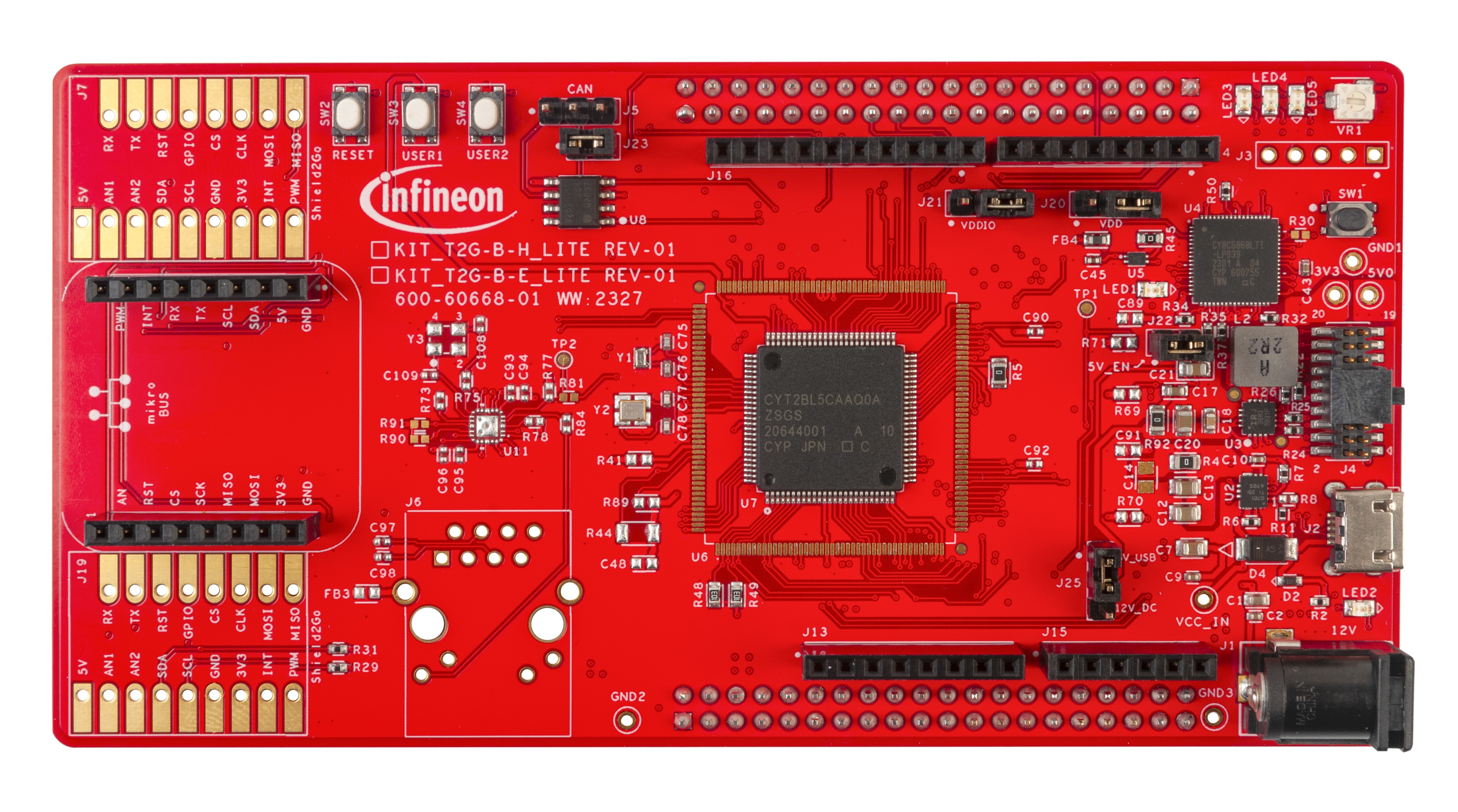
KIT_T2G-B-H-LITE
-
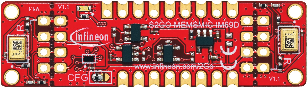
S2GO MEMSMIC IM69D: The S2GO MEMSMIC IM69D integrates two IM69D130 Digital MEMS microphones that generate PDM signals. The S2GO MEMSMIC IM69D includes a PDM to I2S converter, allowing to connect the microphones to the I2S interface of the TRAVEO™ T2G device directly.
-
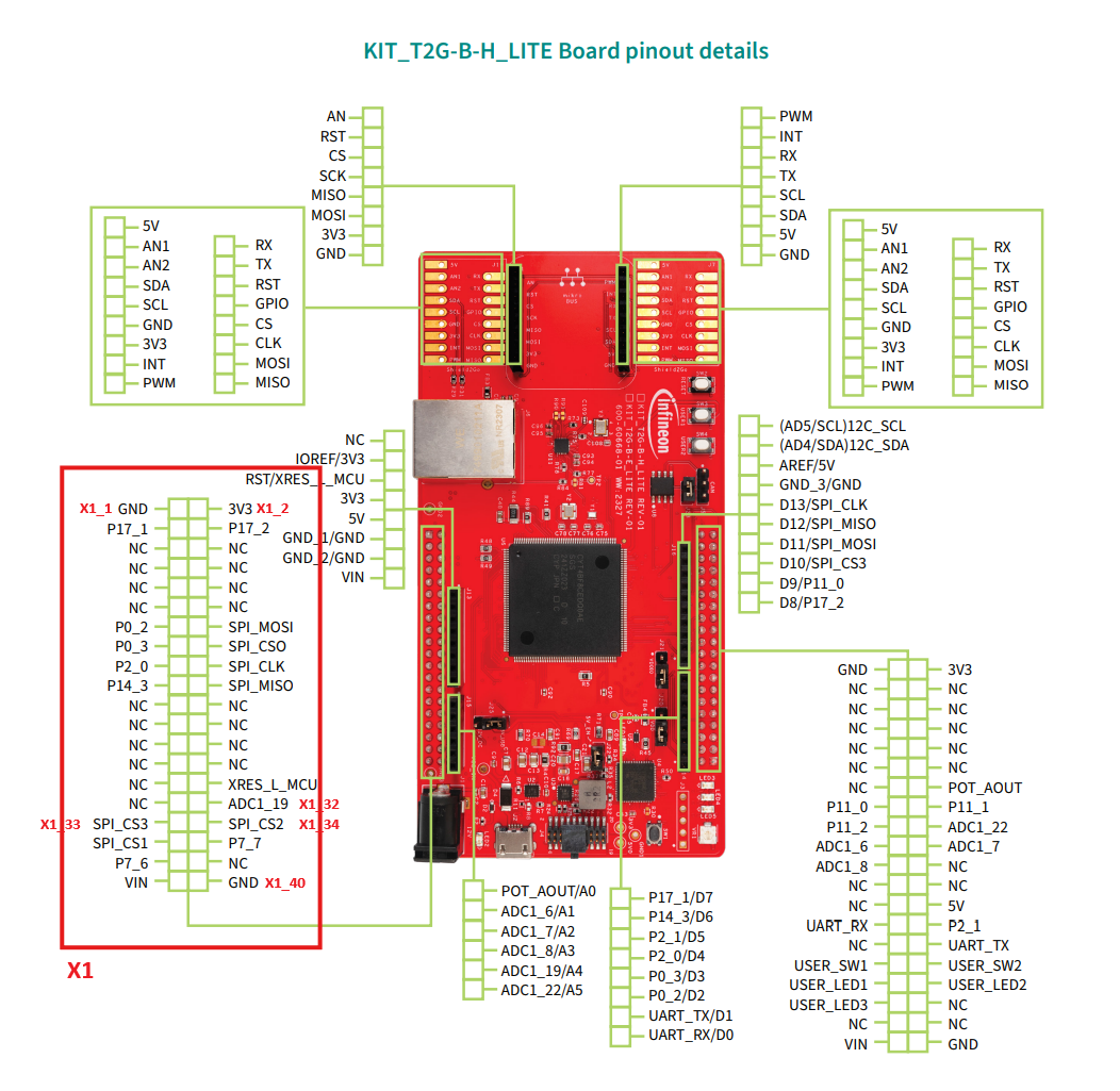
Adapter Board: The S2GO MEMSMIC IM69D cannot be connected to the S2GO interfaces on the board because the I2S-pins do not match. Instead, we will use the following pins on the X1 40-pin header of the KIT_T2G-B-H_LITE.
-
X1_1/GND -> GND
-
X1_2/3V3 -> 3V3
-
X1_32/ADC1_19 -> AUDIOSS1_RX_SDI
-
X1_33/SPI_CS3 -> AUDIOSS1_RX_WS
-
X1_34/SPI_CS2 -> AUDIOSS1_RX_SCK
-
X1_40/GND -> GND
-
Don’t be confused by pins labeled as ADC or SPI. On the MCU, there are more peripherals than pins, so most pins have various functions multiplexed. While the schematic intends to use the pins as ADC or SPI, they can also be used as I2S_RX pins without any issues when configured properly. For detailed functionality of each pin, refer to the datasheet of the device.
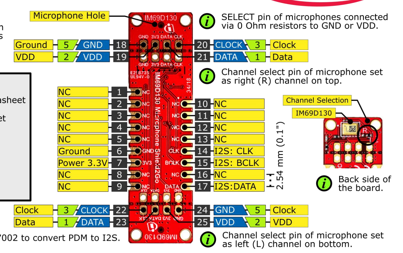
On the S2GO MEMSMIC IM69D, we use the following pins:
- 6 -> GND
- 7 -> 3V3
- 14 -> I2S: CLK
- 15 -> I2S: BCLK
- 17 -> I2S: DATA
 |
|---|
After identifying all relevant pins, we need to make the following connections (left: pin number of S2GO MEMSMIC IM69D, right: pin number of KIT_T2G-B-H_LITE):
- 6 -> X1_1 and X1_40 (connecting only one is also fine)
- 7 -> X1_2
- 14 -> X1_34
- 15 -> X1_32
- 17 -> X1_34
We highly recommend building an adapter board for these connections. When using jumper cables, we found signal integrity issues in our internal testing. For the adapter board, you have two options, either design and manufacture a PCB or manually solder one using pin headers, cables, and a perforated board with copper traces.
For this project, we created a manually soldered board, which looks like this:
Top:
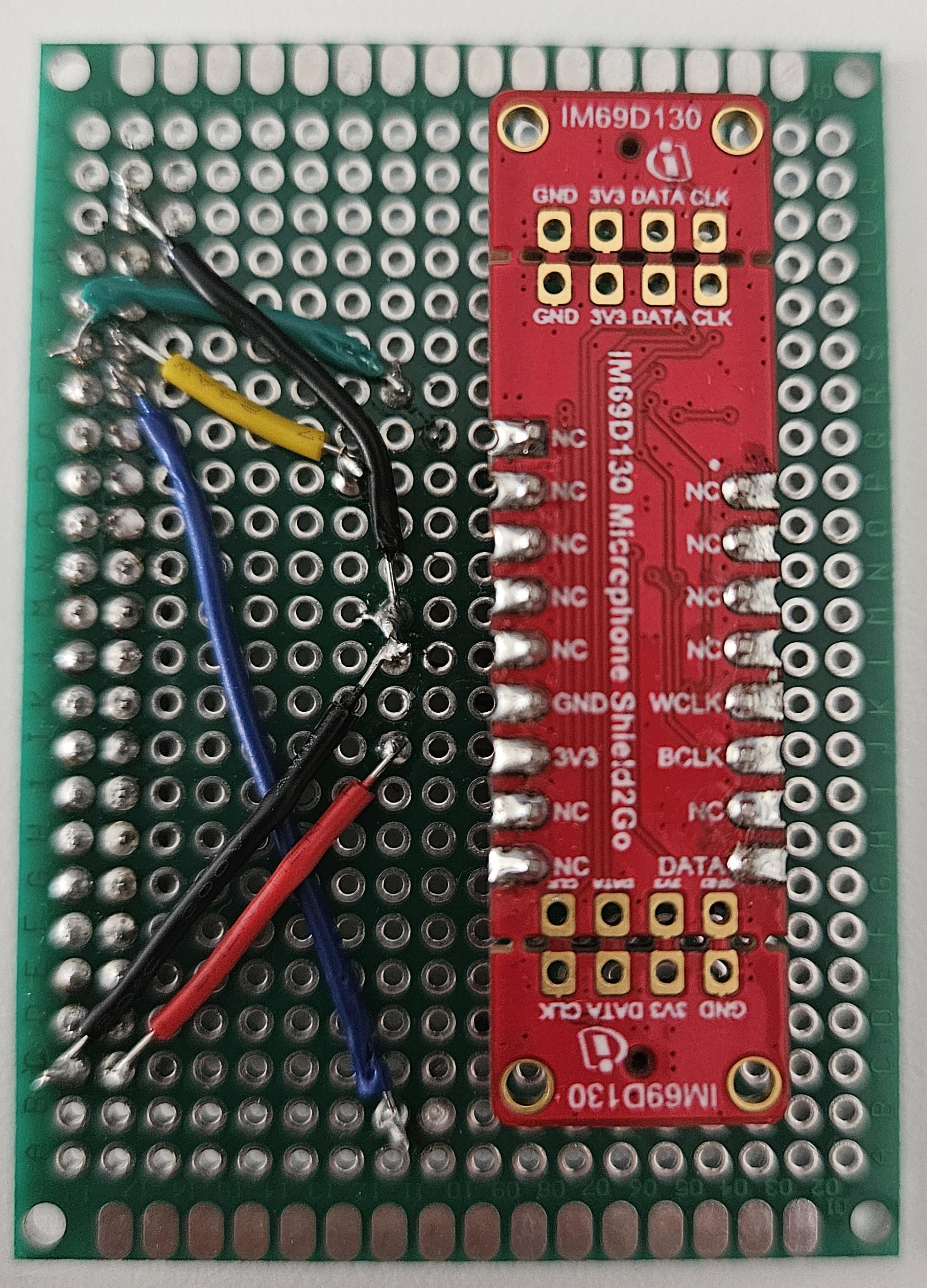
Bottom:
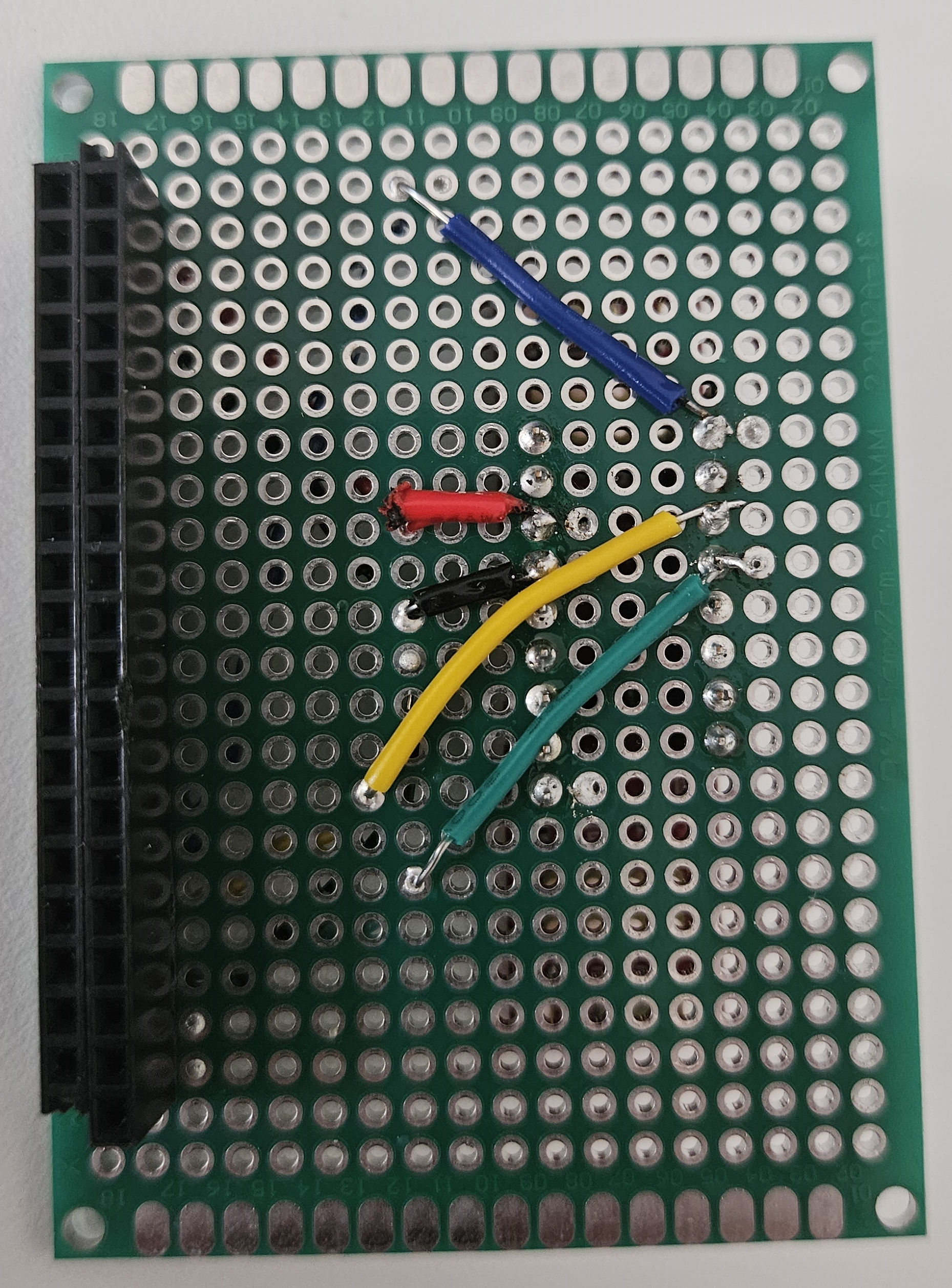
The cable colors represent the following signals:
- Black: GND
- Red: 3V3
- Green: AUDIOSS1_RX_WS/WCLK
- Yellow: AUDIOSS1_RX_SCK/BCLK
- Blue: AUDIOSS1_RX_SDI/DATA
The adapter board is then attached on the bottom side of the board on the X1 header:
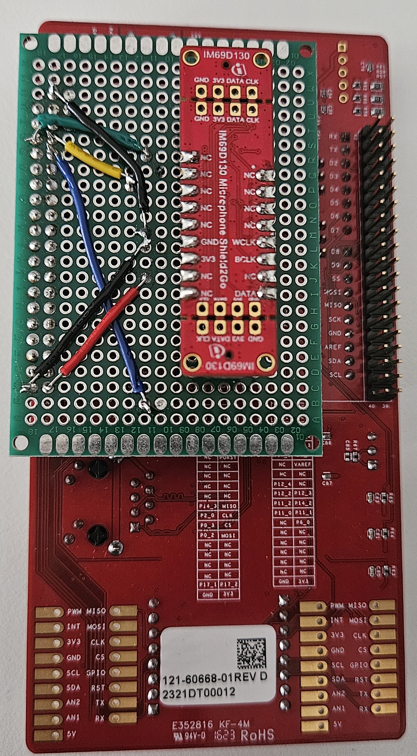
Hardware Setup
For the hardware setup, connect the microphone to the board, and then connect the board to the PC via USB.
Implementation
The application does the following:
- Initialize the board, Imagimob model, UART via retarget-io, and I2S interface
- Using an interrupt, retrieve PCM data from I2S peripheral and store the data in a buffer continuously.
- In a loop:
- converts the sample from I2S buffer to float and scale it to model input range
- inputs sample into the model
- if sufficient samples are available, obtain the classification result
- print the timestamp and classification result via UART to the serial monitor
To configure the I2S peripheral, the device configurator was used and set to the appropriate settings for the S2GO MEMSMIC IM69D. The generated configuration was then copied to main.c for convenience. If you intend to use a different I2S source, you can change the settings accordingly.
Compiling and Running
-
Open ModusToolbox™ > Eclipse IDE for ModusToolbox™ from the Windows Start menu. The Eclipse IDE for ModusToolbox window appears.
-
Browse and select the workspace directory for your project.
-
Click Launch to open the ModusToolbox™ workspace.
-
Select Import Existing Application In-Place from the Quick Panel. The Import ModusToolbox™ Project window appears.
-
Browse and select the code example folder downloaded earlier and click Finish. The code example is imported into the ModusToolbox™.
-
Navigate to the Terminal and run the command make getlibs to ensure all necessary libraries are downloaded.
-
In Launches, click on Generate Launches for SirenDetection_T2GBodyHigh after the libraries are imported.
-
Click on Siren Detection_T2gBodyHigh Program(KitProg3_MiniProg4) to build and flash the application onto the board. You can view the current status in the console.
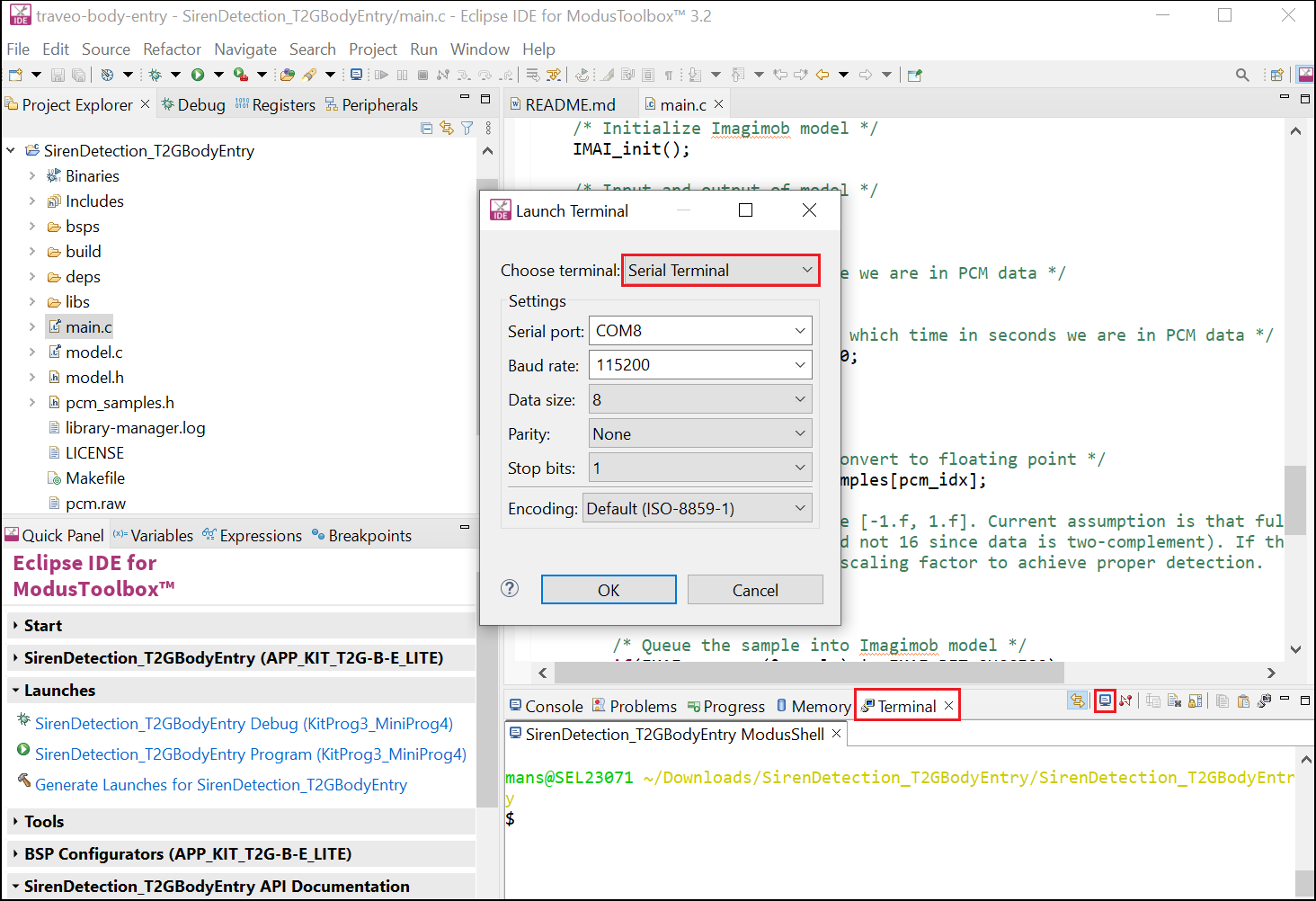
Once the flashing process is complete, you need to open a serial monitor. You have two options: you can either use an external tool like PuTTY (opens in a new tab), or the integrated serial monitor in ModusToolbox™. For latter, click on the terminal window, then on the terminal icon, and select Serial Terminal and configure the following settings:
- Serial port: Choose port of device, depends on local machine
- Baud rate: 115200
- Data size: 8
- Parity: None
- Stop bits: 1
- Encoding: Default (ISO-8859-1)
After completing these steps, you should observe the following output:
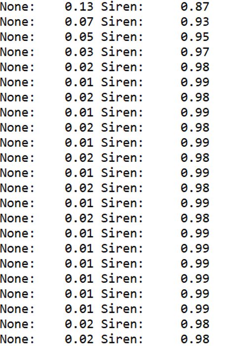
The application continuously analyzes the incoming PCM stream and prints the current timestamp in seconds. If a siren sound is detected with a probability exceeding 70%, the classification results will be printed. If no siren sound is detected, only the timestamps will be printed. For example, an output of None: 0.13 Sound: 0.87 indicates that the model is 87% confident that a siren sound is detected, while the 0.13 represents the confidence level for no siren sound. For testing purposes, this video (opens in a new tab) was played back through mobile phone speakers.