Code Generation for Vision models
This section provides step-by-step information on generating the code for object detection models trained in DEEPCRAFT™ Studio. After you have evaluated the performance of the model, you can convert the model into optimized C-code that can be deployed on PSOC™ Edge device. Graph UX facilitates code generation between any two nodes in a graph with a simple click of a button. You can select the starting and ending nodes in the graph to generate the corresponding C code for model deployment.
Retrieving the trained Object Detection model
-
After the training is complete, download the model from the Imagimob Cloud. Refer Download the Model and Model Predictions for download instructions.
-
Navigate to the project directory, locate and double-click the .tflite file. This opens the .tflite file in Graph UX, which which contains the graph to evaluate the model and generate the code.
Before generating code, let’s understand the graph.
Understanding the Code Generation Graph Flow
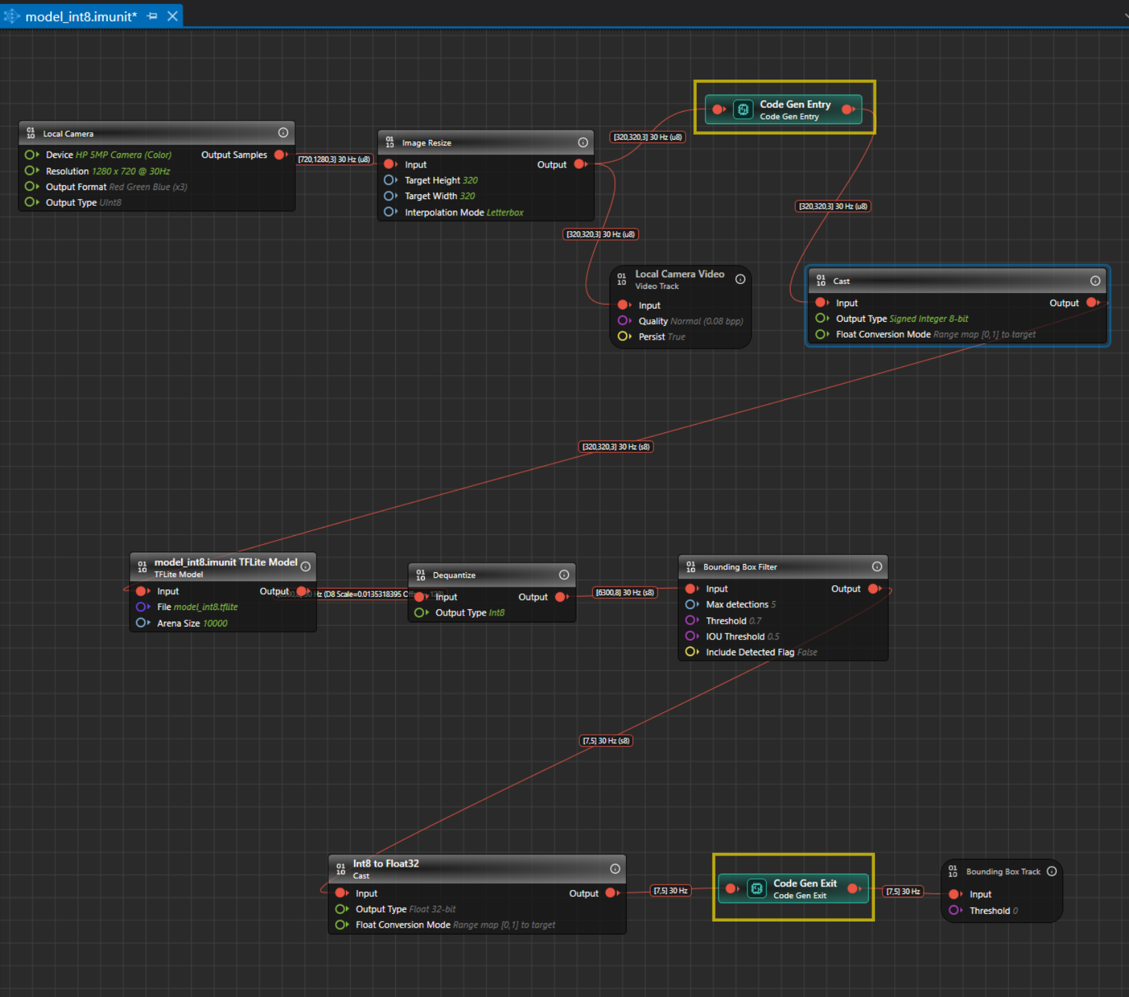
The Model Evaluation Object Detection Graph begins with the Local Camera Node, which streams live video data at the resolution, channel settings and output type specified in the node. For instance, the output shape from the Local Camera Node is [720,1280,3]30 Hz (u8), where 720x1280 represents the video frame dimensions, 3 indicates the RGB color channels, 15 is the frame rate and u8 is the output type in unsigned Integer-8 format. The output from the local camera is input to Image Resize node.
The table represents the default properties of the local camera:
| Local Camera Node | Properties |
|---|---|
| Unit | Unit Name: Displays the name for the unit. This parameter is not editable. Unit Description: Displays the description of the unit. |
| Node | Enabled: Turn the radio button ON or OFF to enable or disable the node respectively. Node Name: Enter the name you want to assign to the node. |
| Inputs | Device: Select the camera for real-time video streaming. Resolution: Select the resolution for real-time video streaming from the list. Output Format: Select the output format from the list. Output Type: Select the output type from the list - UInt8 or Float32. We recommend selecting UInt8, as Float32 tends to be slower. |
| Outputs | Output Type: Displays the output sample. |
The streaming video frames from the local camera node are then passed to the Image Resize Node. The Image Resize node preserves the aspect ratio by scaling the image to fit within the target size and padding the remaining space with a constant color. This approach avoids cropping, stretching, and blurring, which helps the model predict more accurately and consistently. By default, the Image Resize node applies letterbox padding to reach the target input size expected by the model. You can configure the interpolation mode to bilinear or nearest‑neighbor, depending on your performance and quality requirements. For YOLO models, use letterbox because it mirrors the preprocessing typically used during training and aligns with the vision code example, thereby improving inference reliability.
Correct resizing is critical for optimal performance; improper resizing can degrade accuracy, stability, and overall model reliability. In this example graph, the model was trained on images of size 320x320, so the Image Resize Node is set to resize frames to 320x320 automatically. If you are unsure of the expected image size, you can check it on Netron . By default, the settings for the Image pad node is defined. Click the node, if you want to view or edit the settings in the Properties window accordingly.
The table represents the default properties of the Image Resize:
| Image Resize Node | Properties |
|---|---|
| Unit | Unit Name: Displays the name for the unit. This parameter is not editable. Unit Description: Displays the description of the unit. |
| Node | Enabled: Turn the radio button ON or OFF to enable or disable the node respectively. Node Name: Enter the name you want to assign to the node. |
| Inputs | Input: Displays the connection status of the Image Pad node. Target Height: Enter the image height in pixels. Target Width: Enter the image weight in pixels. |
| Interpolation mode | Letterbox: Select this mode if you want to preserve the aspect ratio by scaling the image to fit within the target size and padding the remaining space with a constant color. Nearest-Neighbor: Select this mode if you want to resize by assigning each output pixel the value of the closest input pixel, without any blending. This method is accurate but compute heavy than the bilinear. This method preserves exact pixel values, but it produces blocky, jagged edges and visible aliasing. Bilinear: Select this mode if you want to compute each output pixel by linearly blending the four nearest input pixels along x and y. This yields smoother results with fewer jagged edges but slightly blurs fine details and textures. Used for resizing natural images in classification, detection, or tracking. |
The local camera video track node helps to visualize video data collected from the Image resize node. By default, the settings for the local camera node is defined. Click the node, if you want to view or edit the settings in the Properties window accordingly.
The table represents the default properties of the local camera video track node:
| Local Camera Video Track Node | Properties |
|---|---|
| Unit | Unit Name: Displays the name for the unit. This parameter is not editable. Unit Description: Displays the description of the unit. |
| Node | Enabled: Turn the radio button ON or OFF to enable or disable the node respectively. Node Name: Enter the name you want to assign to the node. |
| Inputs | Input: Displays the connection status of the video track node. Quality: Select the quality (bits per pixel) at which you want to stream the live video. Persist: Displays the output sample. Note:Disabling the Persist option enables real-time video streaming without saving the footage. As a result, replaying or rewinding the video will not be possible. This configuration is optimal for real-time model evaluation when video storage is not required. |
Once resized, the image frames with an input shape of [320,320,3]@15 (u8) are fed to the Cast Node, which convert tensor elements from one type to another. The camera provides unsigned 8-bit values in the range 0–255, while the model in the graph expects signed 8-bit values in the range −128 to 127. To preserve the full dynamic range during integer-to-integer conversion, we apply full-range linear mapping so that 0 maps to −128 and 255 maps to 127. This approach avoids clipping or saturation, maintains the original contrast and detail, and ensures the model receives data in the format it was trained to consume. This conversion stage standardizes the input values to the model’s expected signed domain, improving numerical consistency across inferences. By using full-range mapping, we retain sensitivity to both dark and bright regions, which supports stable predictions. By default, the settings for the Cast node is defined. Click the node, if you want to view or edit the settings in the Properties window accordingly.
The table represents the default properties of the Cast node:
| Cast Node | Properties |
|---|---|
| Unit | Unit Name: Displays the name for the unit. This parameter is not editable. Unit Description: Displays the description of the unit. |
| Node | Enabled: Turn the radio button ON or OFF to enable or disable the node respectively. Node Name: Enter the name you want to assign to the node. |
| Inputs | Input: Displays the connection status of the node. Output Type: Select the target data type for conversion. Float conversion Mode: Select the conversion strategy for the float32 to /from integer conversions. |
The output from the cast node is fed into the model, which detects the classes or objects it was trained on. In this case, the model detects hand gestures such as Rock, Paper and Scissors. The output shape of the model is [6300,8] 30 Hz (D8 scale and offset), where 8 represents the sum of 3 classes(Rock, Paper, Scissors), 4 bounding box coordinates, and 1 Detected Flag option, to detect the validity of each prediction ( 1 for a valid detection; 0 for padding) and 6300 represents the prediction results and D8 contains the information about the scale and offset to convert the quantized values to float 32. By default, the settings for the model node is defined. Click the node, if you want to view or edit the settings in the Properties window accordingly.
The table represents the default properties of the Model node:
| Model Node | Properties |
|---|---|
| Unit | Unit Name: Displays the name for the unit. This parameter is not editable. Unit Description: Displays the description of the unit. |
| Node | Enabled: Turn the radio button ON or OFF to enable or disable the node respectively. Node Name: Enter the name you want to assign to the node. |
| Inputs | Input: Displays the connection status of the node. File: Click the three horizontal dots to browse and select the TensorFlow Lite model you want to evaluate. Arena size: Set the size of the TensorFlow Lite Micro Arena buffer size. To know more, see TensorFlow Lite Micro Documentation. |
The output from the model is fed to the Dequantize node, which convert quantized integers to floating-point values. This conversion provides a more interpretable data type than quantized integers. By default, the settings for the Dequantize node is defined. Click the node, if you want to view or edit the settings in the Properties window accordingly.
The table represents the default properties of the Dequantize node:
| Dequantize Node | Properties |
|---|---|
| Unit | Unit Name: Displays the name for the unit. This parameter is not editable. Unit Description: Displays the description of the unit. |
| Node | Enabled: Turn the radio button ON or OFF to enable or disable the node respectively. Node Name: Enter the name you want to assign to the node. |
| Inputs | Input: Displays the connection status of the node. Output Type: Select the desired output type. By default, Float32 is selected. |
This output shape from the Dequantize node becomes the input for the Bounding Box Filter Node. The Bounding Box Filter Node applies Non-Max Suppression (NMS), a post-processing technique used in object detection algorithms. NMS eliminates redundant overlapping bounding boxes by filtering out those with low confidence scores and selecting only the most confident ones. It sorts the remaining bounding boxes by their confidence scores and iteratively suppresses boxes that overlap significantly with the highest-scoring box. By default, the settings for the Bounding Box Filter node is defined. Click the node, if you want to view or edit the settings in the Properties window accordingly.
The table represents the default properties of the Bounding Box Filter node:
| Bounding Box Filter Node | Properties |
|---|---|
| Unit | Unit Name: Displays the name for the unit. This parameter is not editable. Unit Description: Displays the description of the unit. |
| Node | Enabled: Turn the radio button ON or OFF to enable or disable the node respectively. Node Name: Enter the name you want to assign to the node. |
| Inputs | Input: Displays the connection status of the Image Resize node. Max detections: Enter the number of maximum detections per inference. Threshold: Enter the required confidence for the detection to pass the filter. IOU Threshold: Enter the The IOU threshold. (Intersection over Union) threshold is the Non-Maximum Suppression (NMS) post-processing step is used to determine which bounding boxes to keep or discard. It measures the overlap between two boxes. If the IoU between two boxes exceeds the threshold, the box with the lower confidence score is discarded, keeping only the most confident detection. This helps eliminate redundant or overlapping predictions, ensuring cleaner and more accurate results. A higher IoU score means the predicted box closely matches the actual object, while a lower score indicates less overlap. Typically, IoU thresholds (such as 0.5) are used to determine if a detection is considered correct during both training and evaluation. |
The output from the Bounding Box Filter node is passed to the Int8 to Float32 node, which converts tensor values to the data type expected by the vision code example. The model uses 8-bit signed integer data because it is more memory-efficient and faster to process on the target device. However, the vision code example expects input values in float32 format. To make the output compatible, the 8-bit values are converted to float32. During conversion, the input range 0–255 is mapped linearly to the expected float32 range 0 to 1. By default, the settings for the Int8 to Float32 node is defined. Click the node, if you want to view or edit the settings in the Properties window accordingly.
The table represents the default properties of the Cast node:
| Cast Node | Properties |
|---|---|
| Unit | Unit Name: Displays the name for the unit. This parameter is not editable. Unit Description: Displays the description of the unit. |
| Node | Enabled: Turn the radio button ON or OFF to enable or disable the node respectively. Node Name: Enter the name you want to assign to the node. |
| Inputs | Input: Displays the connection status of the node. Output Type: Select the target data type for conversion. Float conversion Mode: Select the conversion strategy for the float32 to /from integer conversions. |
The output from the Int8 to Float32 Node is then fed to the Bounding Box Track Node, which displays the bounding boxes. The input shape for this node should be [Confidence, Detection], where Confidence includes (Center X, Center Y, Width, Height, ClassN…). These bounding boxes are finally displayed on the Video Track Node on the timeline, allowing you to visualize the model in action with live streaming video data and bounding boxes drawn on the detected objects. By default, the settings for the Bounding Box Track node is defined. Click the node, if you want to view or edit the settings in the Properties window accordingly.
The table represents the default properties of the Bounding Box Track node:
| Bounding Box Track | Properties |
|---|---|
| Unit | Unit Name: Displays the name for the unit. This parameter is not editable. Unit Description: Displays the description of the unit. |
| Node | Enabled: Turn the radio button ON or OFF to enable or disable the node respectively. Node Name: Enter the name you want to assign to the node. |
| Inputs | Input: Displays the connection status of the Image Resize node. Threshold: Enter the threshold value below which the bounding boxes will be ignored. |
How to generate the code?
With the introduction of the Callback C API, Graph UX now uses Code Gen Entry and Code Gen Exit nodes to define which part of the graph is included in code generation. This replaces the previous workflow, where you selected input and output nodes for code generation.
In the new workflow, insert Code Gen Entry and Code Gen Exit nodes to define the part of the graph to be used for code generation. The nodes between the Code Gen Entry and Code Gen Exit nodes are included in the generated code.
A graph must include at least one Code Gen Entry node and one Code Gen Exit node. You can add more entry or exit nodes depending on your application. This supports different graph configurations, including:
- Single input and single output
- Multiple inputs and single output
- Single input and multiple outputs
- Multiple inputs and multiple outputs
Multiple Code Gen Entry nodes let you combine data from different paths, such as multiple sensors. Multiple Code Gen Exit nodes let you generate outputs from different parts of the graph, which can support use cases such as running multiple models in parallel or exposing intermediate outputs for debugging.
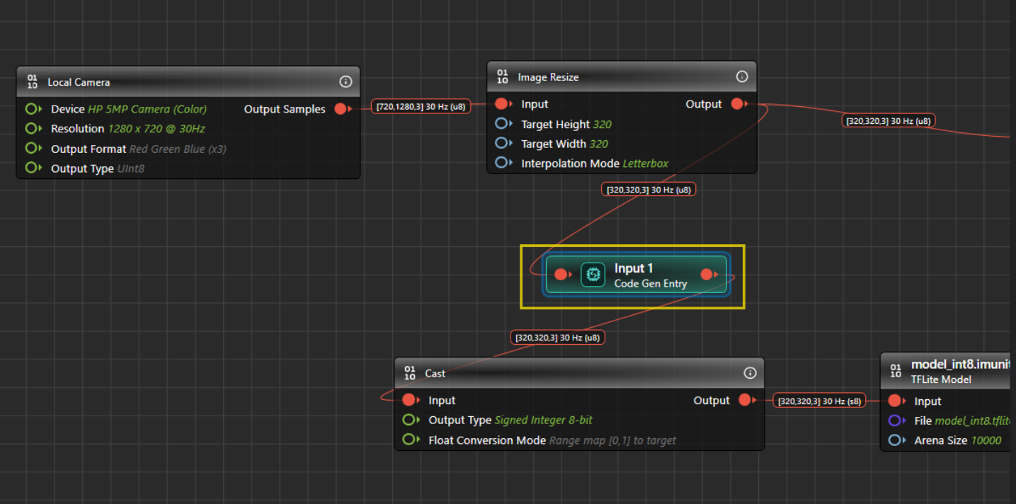
For vision models, Graph UX automatically adds the Code Gen Entry and Code Gen Exit nodes when you open a .tflite file for code generation for the first time. The nodes placed between the Code Gen Entry and Code Gen Exit nodes are included in code generation. In this graph, the Code Gen Entry node is placed before the cast node, and the Code Gen Exit node is placed before the bounding box track node.
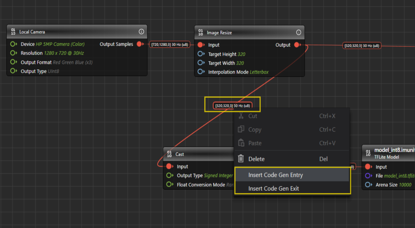
If you want to generate code for a different section of the graph, move or add the Code Gen Entry and Code Gen Exit nodes at the desired nodes. To add a Code Gen Entry node, right-click on the connection before the node where code generation should start, and select Insert Code Gen Entry Node. To add a Code Gen Exit node, right-click the connection after the node where code generation should end, and select Insert Code Gen Exit Node.
If you used the .tflite file for code generation before this change, you may need to add these nodes manually. For vision models, add the Code Gen Entry node before the cast node and the Code Gen Exit node before the bounding box track node.
After you have placed the code gen entry and exit nodes, lets configure the code generation parameters.
To generate the code, follow the steps:
-
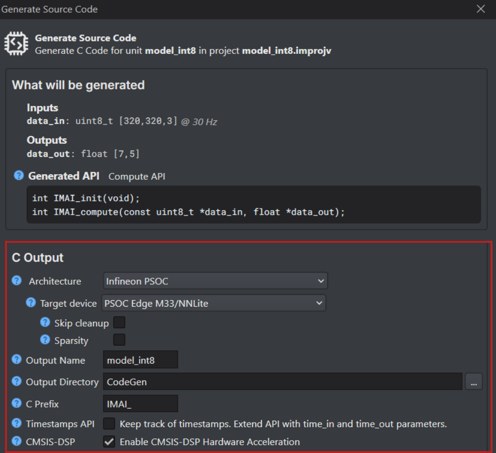
Navigate to the toolbar and click the Generate Source Code button. The Generate Source Code window appears. The Generate Source Code window displays the model inputs, model outputs, and the API style that will be used for code generation, as shown below:
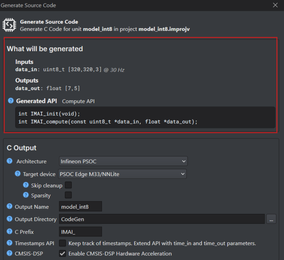
DEEPCRAFT™ Studio automatically generates one of three public C API styles: Function, Queue, or Callback, based on your model’s structure. The Queue and Callback APIs support both timestamp and non-timestamp variants. When more than one API style is available in Graph UX, you can select the preferred style in the Generate Code template. For more information, refer to Edge API.
-
Configure the following parameters:
-
In Architecture, select Infineon PSOC as the architecture type.
-
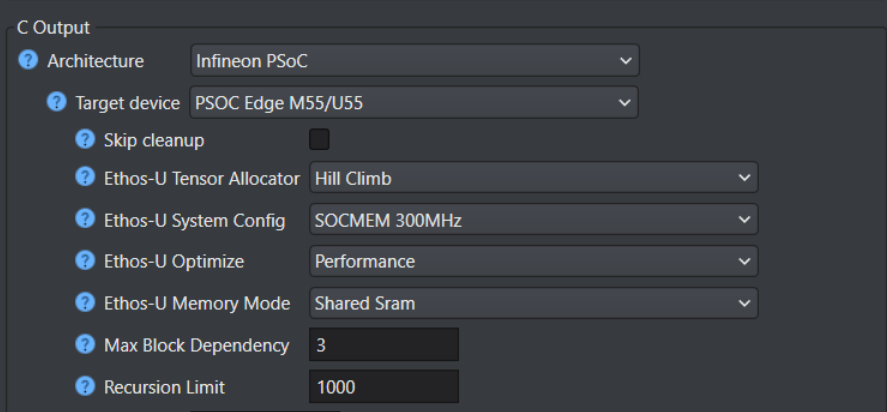
In Target Device, select the required Infineon board or core type from the following options - PSOC Edge M33/NNLite, PSOC Edge M55/U55 or PSOC Edge M55.
Before generating code for PSOC targets, ensure that your model only uses the layers and operators listed as supported in the Supported layers and operators for PSOC Targets table. If your model contains any layers or operators that are not supported, select the ANSI C99 architecture type. For instructions on generating code using the ANSI C99 architecture, refer to Code Generation for Other Development Boards.
-
Select the Skip Cleanup checkbox to not delete the certain temporary files created during code generation. If necessary, you can delete these files manually at a later time. When this checkbox is disabled, the temporary files are deleted automatically.
-
Select the Enable Sparsity checkbox to further optimize the model by packing sparse weights, thereby saving memory when deploying the model on the target device. This option is available only when PSOC Edge M33/NNLite is selected.
Advanced optimization for PSOC™ Edge M55+U55
The following optimization settings are part of the Vela compiler and generate optimizations for code targeting the Ethos-U55 NPU. These options reduce scratch memory usage with minimal to no impact on model accuracy.
| Parameters | Description |
|---|---|
| Ethos-U Tensor Allocator | Select Linear Alloc, Greedy or Hill Climb to specify the algorithm for allocating non‑constant tensors on the NPU and CPU. By default, Hill Climb is selected. |
| Ethos-U System Config | Select SOCMEM 300MHz or SOCMEM 200MHz as the system configuration of the Ethos-U NPU. Refer to Silicon documentation to know more. |
| Ethos-U Optimize | Select the optimization strategy based on Size or Performance. The Size strategy ensures minimal RAM usage by avoiding the use of the arena cache memory area size whereas the Performance strategy prioritizes maximal performance by utilizing the specified arena cache memory area size. By default, Performance strategy is selected. |
| Ethos-U Memory Mode | Select Shared SRAM or SRAM Only as the memory mode. Shared SRAM is shared between Ethos-U and Cortex-M software, whereas SRAM Only is dedicated to Ethos-U. The non-SRAM memory is read-only. By default, Shared SRAM is selected. |
| Arena Cache Strategy | Select the strategy to determine the arena cache size for Ethos-U55 NPU memory optimization: Min , Max or Custom. - When you select Min, the arena cache size is set to the minimum size required by the model. - When you select Max, the arena cache size is set to the maximum size allowed by the target platform. This is the default strategy. - When you select Custom, the arena cache size is set to the specified size manually. When this option is selected, the Arena Cache Size parameter becomes available. |
| Arena Cache Size | Set the size of the arena cache memory area, in bytes. The size of the arena cache memory area must be any integer greater than or equal to 0. By default, the value of arena cache memory is set as 2936012. The arena cache is an optimization hint for U55 acceleration. It is not the same as the overall tensor arena used by the model. |
| Force Python Backend | Enable this option to force the use of the deprecated Vela Python API backend for model optimization. When selected, additional advanced parameters related to the Python backend optimization flow are available, such as Max Block Dependencies and Recursion Limit. |
| Recursion Limit | Set the Python internal limit to depth of recursion. For very large networks, increasing the recursive limit may be necessary due to the recursive graph traversal algorithm. If generation fails with a RecursionError, increase the limit using this option. By default, the recursion limit is set as 1000. This option is applied only when the Force Python Backend option is enabled. |
| Max Block Dependency | Set the maximum value that can be used for the block dependency delay between NPU kernel operations. A lower value may result in longer execution time. You may set: 0, 1, 2 or 3 as the value for Npu block dependency. By default, the value of block dependency is set as 3. This option is applied only when the Force Python Backend option is enabled. |
-
In Output Name, enter the name of the output files.
-
In Output Directory, browse and select the directory where you want to save the generated code. By, default Firmware is selected as the default folder.
-
In C Prefix, enter the prefix to be added at the beginning of the generated file names.
-
In Timestamps API, enable the checkbox to track corresponding input time for each output prediction. To know about the edge API, refer to Edge API.
-
In CMSIS-DSP, enable the checkbox to optimize the code using the ARM CMSIS-DSP Library. The code will be hardware accelerated using the CMSIS-DSP library for compatible nodes.
-
Click Ok to generate the code. The code generation may take some time. The code (model.c and model.h files) is generated in the Output Directory defined earlier.
After you have generated the code, refer to the Deploy Vision Model on PSOC™ Edge boards to know the deployment steps.