Graphical User Interface
This section provides step-by-step information on generating, optimizing and validating the code for Infineon targets PSOC™ 6, PSOC™ Edge M55, PSOC™ Edge M55+U55, PSOC™ Edge M33+NNLite using the Graphical User Interface (GUI).
Code Generation Workflow
This is the workflow for generating code using DEEPCRAFT™ Model Converter:
-
Generate Code: Convert your model (.keras, .h5, .tflite, or .pt2) into (.c) and (.h) files which you can deploy onto the Infineon board.
-
Optimize the Model: Use calibration data to apply quantization.
-
Validate the Model: Test the quantized or non-quantized model using validation data to ensure accuracy.
Model Converter does not support code generation for PyTorch models with multi-inputs and multi-outputs.
Launch Graphical User Interface
After you download and install the DEEPCRAFT™ Model Converter executable file, the DEEPCRAFT™ Model Converter GUI mode will launch automatically.
Pre-requisites for the PyTorch Models
When generating the code for PyTorch models, you must select one of the following options: Cloud-Based Code Generation or Container-Based Code Generation.
The selection of the Cloud-Based Code Generation and Container-Based Code Generation is required only for the PyTorch Models.
Cloud-Based Code Generation
When you select Cloud-Based Code Generation, the PyTorch model is uploaded to the Imagimob Cloud for code generation. For selecting the Cloud-Based Code Generation, follow the steps:
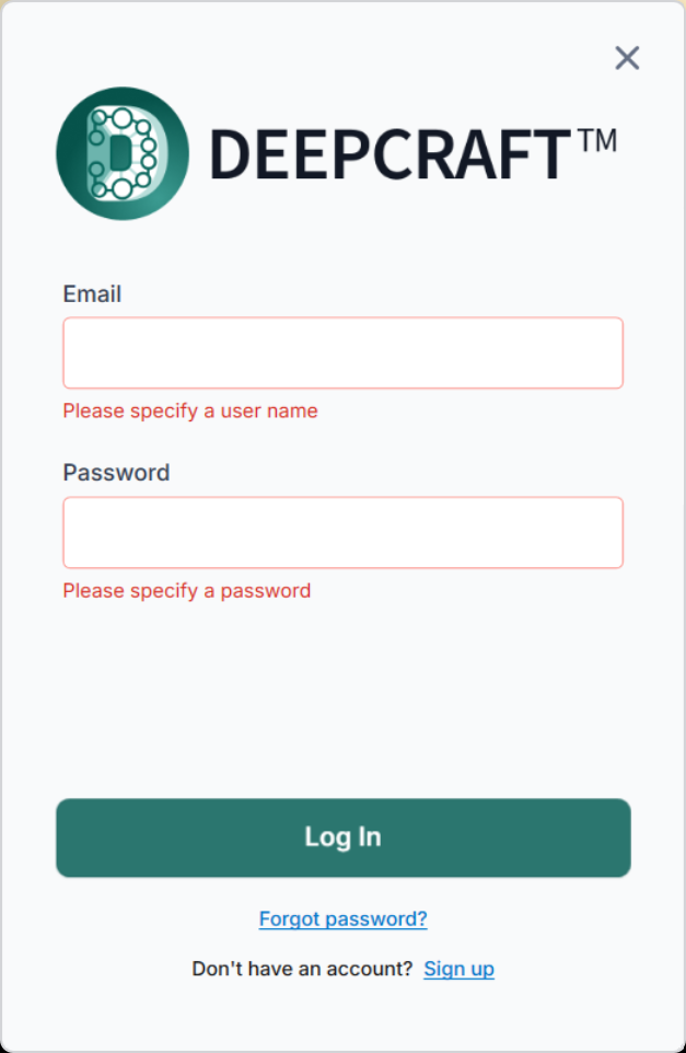
- Click Sign In at the top right of the application to open the sign-in window.
- Enter the Imagimob email and password to login.
- If you do not have an account, create one here .
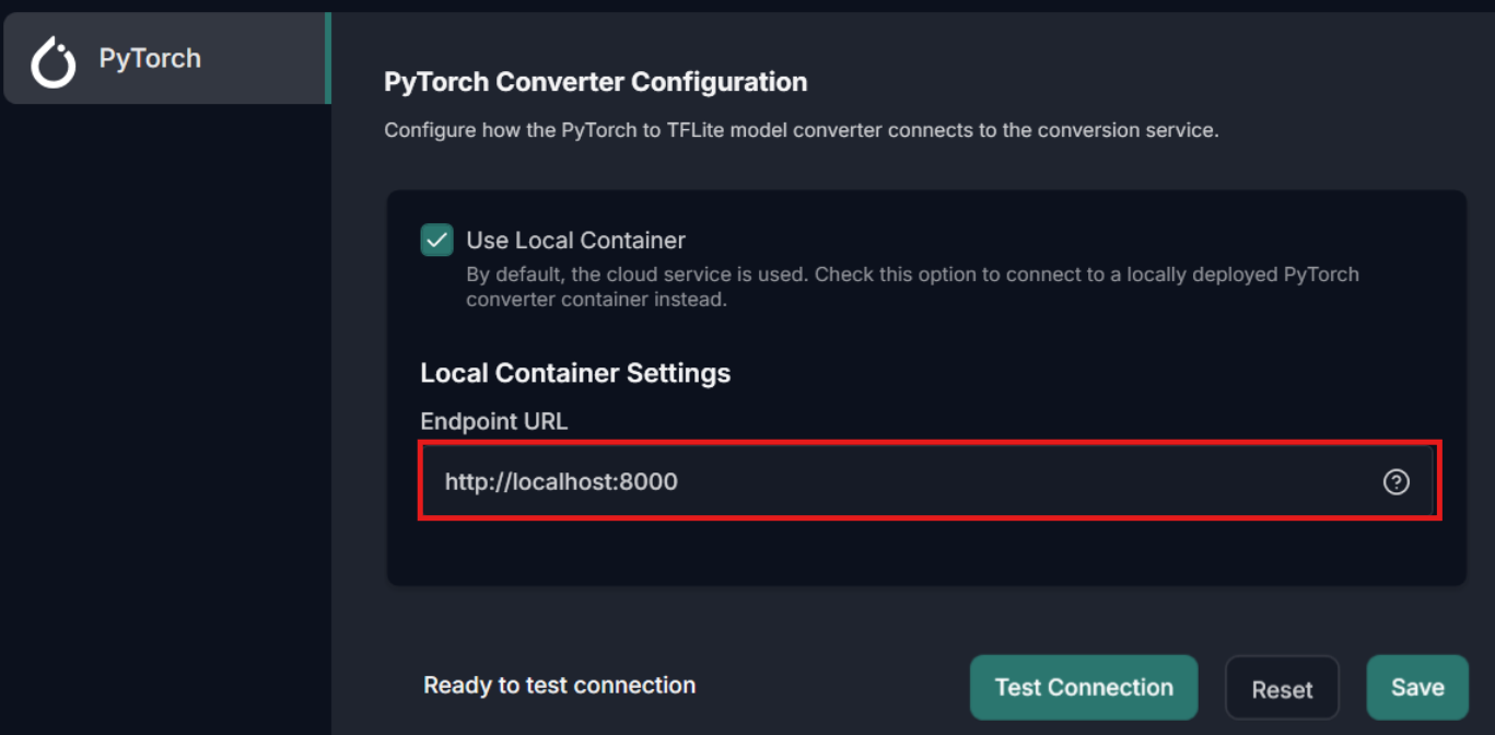
Container-Based Code Generation
When you select Container-Based Code Generation, the PyTorch model is not uploaded to the Imagimob Cloud and code generation runs locally using a downloaded PyTorch Converter Container.
Before using this option, make sure you have setup the PyTorch Converter Container. You can either setup Docker or Podman Container as per your requirement. Refer to Setup Docker or Podman Container for the detailed steps.
For selecting the Container-Based Code Generation, follow the steps:
-
Go to Tools> Options> PyTorch and enable the Use Local Container checkbox to connect to a locally deployed PyTorch Converter Container.
-
In Local Container Settings> Endpoint URL enter the url of the PyTorch Converter Container and click Save.
-
Click Test Connection to verify connectivity between the Model Converter and the PyTorch Converter Container.
Configure the Project File
Lets configure the parameters in the template and save the template as Bring Your Own Model project file (.byom) to generate, optimize, and validate the model. You can reuse this project file to generate the code later. To know more, refer to Working with project files.
This video provides a concise, visual introduction to the workflow described in this documentation.
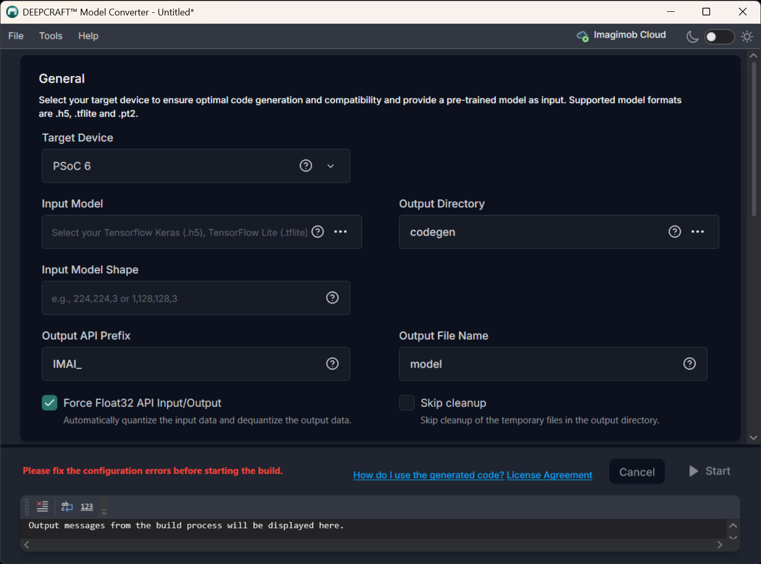
General
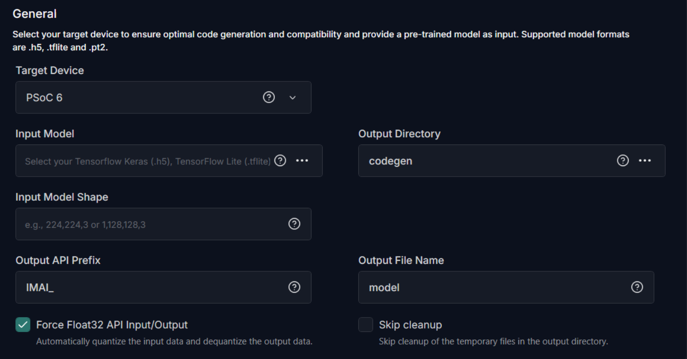
To generate code for the model, configure the following:
-
Target Device: Select the required Infineon board or core type from the following options - PSOC 6, PSOC Edge M55, PSOC Edge M33 with NNLite, PSOC Edge M55 with U55.
-
Input Model: Click the three horizontal dots to browse and select the model file for which you want to generate the code. You can choose from TensorFlow Keras (.h5), TensorFlow Keras (.keras) TensorFlow Lite (.tflite), or PyTorch (.pt2) model formats.
-
Output Directory: Click the three horizontal dots to browse and select the directory where you want to save the generated code. By default, the application selects Codegen as the default folder for saving the generated code.
-
Output API Prefix: Enter the prefix to be added at the beginning of the generated API functions.
-
Override Arena Size: By default, this parameter is set to 0 to enable automatic calculation of the arena size. However, if the model fails to initialize on the embedded device and crashes during initialization (IMAI_int()), modify the arena size value. Increase in increments of 4096 bytes from the default calculated size. When you find a working value, decrease in steps of 1024 bytes or less to determine the minimum stable size that does not crash. The calculated arena size can be found in the code_generation_report.md under the Scratch memory column in the Memory Usage section. Refer to Insufficient model arena memory during deployment for detailed information.
-
Output File Name : Enter the name of the output file.
-
API Input/ Output Data Auto Quantization : Enable the checkbox to automatically quantize the input data and de-quantize the output data to Float32 format. If your real world input data is not in float32 format, do not enable this checkbox.
-
Interpreterless: Enable the checkbox to generate the static C++ code that executes the neural network directly. The interpreterless mode pre-interprets the model, removing the need for the TensorFlow Lite Micro interpreter at runtime. When this option is enabled, the runtime, memory planner and unused operator code, memory planner are not compiled into the final application, reducing the ROM footprint. This can provide memory savings for very small models (under 400 KB) that use a limited set of operator types. The exact amount of memory saved may vary from model to model but in some cases can be close to ~200KB.
Interpreterless mode is supported on PSOC™ 6, PSOC™ Edge M33+NNLite targets only.
-
Model is RNN: Enable this checkbox when the model includes recurrent layers (such as LSTM, GRU, or similar). The toolchain attempts to detect this automatically from the model file, but setting the option explicitly is recommended. This setting does not affect model conversion but only controls how validation and calibration data are handled for streaming models. To know more about this option, refer to Streaming RNN model validation.
-
Use zero-copy output API: The zero-copy output API returns pointers to internal buffers where the outputs of the model are stored so you can access the results directly. This avoids copying the outputs to the user-provided external buffers, which is the default behavior.
You cannot enable API Input/ Output Data Auto Quantization and Use zero-copy output API at the same time.
-
Skip Cleanup: Enable the checkbox if you do not want the application to delete certain temporary files created during code generation. If necessary, you can delete these files manually at a later time. When this checkbox is disabled, the application will automatically delete the temporary files.
After setting the parameters, you have two options: optimize the model or proceed without optimization, depending on your requirements. If you select not to optimize, you can directly generate the code. However, if you prefer to optimize and validate the model, follow the steps to set the optimization and validation parameters before generating the code.
File specifications for calibration and validation
Before starting model optimization and validation, prepare the calibration and validation data. Calibration data is used to quantize the model, while validation data is used to evaluate the model. For models with a single input and single output, select one of the following data sources: Compressed NumPy (.npz), CSV, or a Recursive Directory. For models with multiple inputs and outputs, use Compressed NumPy (.npz) only, as no other data sources are supported. Specifications for Compressed NumPy file, CSV file or Recursive Directory are listed in Supported Data Formats.
The calibration dataset should be diverse and representative of expected inputs, including edge cases and extremes. It is recommended not to use the validation dataset for calibration to avoid bias and maintain an unbiased evaluation.
Model Optimization
Model optimization involves refining the code to enhance performance, efficiency, and accuracy of the model on the Infineon targets. It reduces computational cost, shortens inference time, and reduces memory footprint to deliver reliable performance across environments.
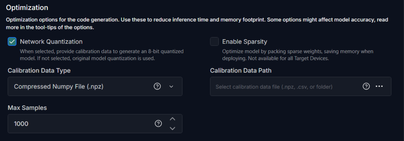
To optimize the model, configure the following:
-
Enable Network Quantization: Enable the checkbox, if you want to quantize the network code. If you enable this option, you must provide calibration data to generate a 8-bit quantized model.
-
Enable Sparsity: Enable the checkbox to further optimize the model by packing sparse weights, thereby saving memory when deploying the model on the target device.
-
Max Samples: Enter the maximum number of samples to use for calibration. If the number of samples in the provided dataset exceeds this value, the dataset will be truncated to the first N samples.
-
Quantization Type: Select the quantization type as Int8x8 or Int16x8.
In Int8x8 quantization, both weights and activations are quantized to 8-bit integers (Int8). Int8x8 quantization reduces the time consumption and minimizes memory and bandwidth usage but at the cost of some accuracy. In Int16x8 quantization, weights are quantized to 8-bit integers (Int8), but activations are quantized to 16-bit integers (Int16).
Int16x8 quantization can provide higher accuracy with only a marginal increase in compute time, model binary size, and work-buffer memory by storing intermediate values in 16-bit integers rather than 8-bit. However, the benefit is model-dependent, so you must evaluate Int8x8 and Int16x8 side by side to determine which configuration suits your needs.
You can generate the code twice — first with Int8x8 quantization, then with Int16x8 quantization and compare the results side by side in the Output window. For complex models, review quantitative metrics (for instance, see the validation results) in the
code_generation_report.mdfile to assess differences.
NPUs accelerating neural network inference only accelerate int8x8 or int16x8 layers, float32 layers will fall back to the MCU.
-
Calibration Data Type: Select the calibration data source as one of the following: Compressed NumPy file (.npz), CSV file, or a directory. For models with multiple inputs and outputs, use Compressed NumPy (.npz) only, as no other data sources are supported.
-
Recursive Directory Search: Select this option to load calibration data from a directory.
-
CSV File: Select this option to load calibration data from a CSV file.
-
Compressed NumPy File (.npz) File: Select this option to load calibration data from a compressed NumPy file.
Refer to Supported Data Formats to know the specifications for Compressed NumPy file, CSV file or Recursive Directory.
-
-
Calibration Data Path: Click the three horizontal dots to browse and select the CSV file, compressed NumPy file or directory corresponding to the selected calibration data type.
Advanced optimization for PSOC™ Edge M55+U55
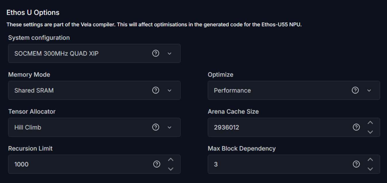
The following optimization settings are part of the Vela compiler and generate optimizations for code targeting the Ethos-U55 NPU. These options reduce scratch memory usage with minimal to no impact on model accuracy.
-
System Configuration: Select SOCMEM 300MHz QUAD XIP or SOCMEM 200MHz QUAD XIP as the system configuration of the Ethos-U NPU. Refer to Silicon documentation to know more.
-
Memory Mode: Select Shared SRAM or SRAM Only as the memory mode. Shared SRAM is shared between Ethos-U and Cortex-M software, whereas SRAM Only is dedicated to Ethos-U. The non-SRAM memory is considered read-only. By default, Shared SRAM is selected.
-
Optimize: Select the optimization strategy based on Size or Performance. The Size strategy ensures minimal RAM usage by avoiding the use of the arena cache memory area size whereas the Performance strategy prioritizes maximal performance by utilizing the specified arena cache memory area size. By default, Performance strategy is selected.
-
Tensor Allocator: Select Linear Alloc, Greedy or HillClimb to specify the algorithm for allocating non‑constant tensors on the NPU and CPU. By default, HillClimb is selected.
-
Arena Cache Size: Set the size of the arena cache memory area, in bytes. The size of the arena cache memory area must be any integer greater than or equal to 0. By default, the value of arena cache memory is set as 2936012.
-
Recursion Limit: Set the Python internal limit to depth of recursion. For very large networks, increasing the recursive limit may be necessary due to the recursive graph traversal algorithm. If generation fails with a RecursionError, increase the limit using this option. By default, the recursion limit is set as 1000.
-
Max Block Dependency: Set the maximum value that can be used for the block dependency delay between NPU kernel operations. A lower value may result in longer execution time. You may set: 0, 1, 2 or 3 as the value for Npu block dependency. By default, the value of block dependency is set as 3.
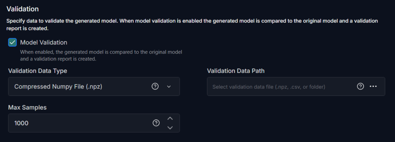
Model Validation
Model validation evaluates the optimized model to the original baseline and generates a report. The report summarizes how closely the converted model’s predictions match your reference outputs along with other validation metrics. You can validate both quantized and non-quantized models without connecting to a actual device.
To validate the model, configure the following:
-
Model Validation: Enable the checkbox, if you want to validate the model.
-
Validation Data Type: Select the validation data source as one of the following: Compressed NumPy file (.npz), CSV file, or a directory. For models with multiple inputs and outputs, use Compressed NumPy (.npz) only, as no other data sources are supported.
-
Recursive Directory Search: Select this option to load calibration data from a directory.
-
CSV File: Select this option to load calibration data from a CSV file.
-
Compressed NumPy File (.npz) File: Select this option to load calibration data from a compressed NumPy file.
Refer to Supported Data Formats to know the specifications for Compressed NumPy file, CSV file or Recursive Directory.
-
-
Validation Data Path: Click the three horizontal dots to browse and select the CSV file, compressed NumPy file or directory corresponding to the selected validation data type.
-
Max Samples: Enter the maximum number of samples to use for validation. If the number of samples in the provided dataset exceeds this value, the dataset will be truncated to the first N samples. For on-device profiling, select a smaller value to ensure the data fits on the target device.
-
Default: Select this option to validate the generated model against the desktop TFLite interpreter. The Model Converter first runs the float TFLite model on the validation dataset and uses the outputs as the reference baseline, then compares the quantized variants (INT8×8 and INT16×8) against that float baseline during desktop validation. For on-device profiling, the generated
.hfiles use the selected deployment quantization level (float, INT8×8, or INT16×8). This option is recommended for most workflows.
Desktop validation is not available for PSOC™ Edge M55+U55 target.
- Use Provided Reference: Select this checkbox to use the output data in the validation file as the reference. The Model Converter reads the reference outputs directly from the validation NPZ file instead of generating reference data by running model inference. Use this option when the validation dataset includes precomputed ground-truth outputs (for example, from a simulation, a reference implementation, or the original training framework) and you want to validate the on-device model against those outputs rather than against TFLite. Refer to NPZ Data Formats to know the specifications for Compressed NumPy file in detail.
After configuring the project file, navigate to File> Save and assign a descriptive name to save the project file (.byom). This lets you reuse the configuration later without re-entering options. See Working with project files for code generation to know more.
Generate Code for the Model
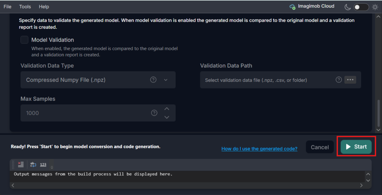
Click the Start button to generate the code for the model. The code (model.c/.h files) is generated in the Output Directory defined earlier along with the code generation report. You can also view the validation and optimization results in the output window at the bottom of the model converter.
After generating the code for the model, let’s deploy the code on the Infineon boards using the ModusToolbox™. To know how refer to Deploy model on PSOC™ Edge using the Code Examples.
Working with project files for code generation
To streamline code generation for multiple models, you can capture your settings in project file (.byom). You can open the project file with the saved configuration later either in the GUI or from the CLI without re-entering options. Below is a compact workflow and some best practices to help you organize and reuse configurations effectively.
-
Save your configuration: After configuring code-generation options for a model, navigate to File> Save and assign a descriptive name to the project file.
-
Reuse an existing configuration: To re-generate code using saved configuration, navigate to File> Open, browse and select the required project file.
-
Create a new configuration for another model: Navigate to File> New to open a new project file and configure the code generation settings for the model, and save as a project file.
-
Maintain multiple configurations: Keep separate project files for different models or targets. Open the one you need whenever you want to generate code for that setup.
-
Use from the command line: The project files can also be used from the CLI, which helps avoid retyping long command strings. Refer to the CLI documentation for instructions on loading a saved project file and running code generation in command-line mode.
Whats Next?
After you have generated, optimized and validated the code for your model, the next step is to deploy the code onto the Infineon boards using ModusToolbox™. To learn how to deploy the code, refer to Deploy model on PSOC™ Edge using the Code Examples.